65-2482RK Multi Point Detector Operator’s Manual Part Number: 71-0205RK Revision: A Released: 7/18/14 RKI Instruments, Inc. www.rkiinstruments.
WARNING Read and understand this instruction manual before operating detector. Improper use of the detector could result in bodily harm or death. Periodic calibration and maintenance of the detector is essential for proper operation and correct readings. Please calibrate and maintain this detector regularly! Frequency of calibration depends upon the type of use you have and the sensor types.
Product Warranty RKI Instruments, Inc. warrants gas alarm equipment sold by us to be free from defects in materials, workmanship, and performance for a period of one year from date of shipment from RKI Instruments, Inc. Any parts found defective within that period will be repaired or replaced, at our option, free of charge.
Table of Contents Overview . . . . . . . . . . . . . . . . . . . . . . . . . . . . . . . . . . . . . . . . . . . . . . . . . . . . . . . . . . . . . . . . . . . 1 Specifications. . . . . . . . . . . . . . . . . . . . . . . . . . . . . . . . . . . . . . . . . . . . . . . . . . . . . . . . . . . . . . . . 1 Description . . . . . . . . . . . . . . . . . . . . . . . . . . . . . . . . . . . . . . . . . . . . . . . . . . . . . . . . . . . . . . . . . . 3 Detectors. . . . . . . . . . . . . . . . . . . . . . . . .
Overview This manual describes the 65-2482RK multi point direct connect detector. This manual also describes how to install, start up, maintain, and calibrate the detector when it is used with a gas monitoring controller. A parts list at the end of this manual lists replacement parts and accessories for the detector. Specifications WARNING: Do not use this product in a manner not specified in this instruction manual. Table 1 lists specifications for the multi-point detector.
NOTE: The following symbol on the detector label is a caution to the user to refer to this documentation for installation and operation instructions: ! WARNING: When using the 65-2482RK, you must follow the instructions and warnings in this manual to assure proper and safe operation of the 65-2482RK and to minimize the risk of personal injury. Be sure to maintain and periodically calibrate the 65-2482RK as described in this manual.
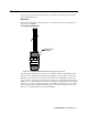
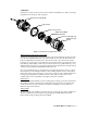
Description This section describes the multi-point detector. It consists of the detectors, the terminal strip, and the junction box. Detectors This section describes the components of the various detectors that are used with each model of the 65-2482RK. 61-0190RK-CH4 IR Detector IR LEL CH4 Detector Figure 1: 61-0190RK-CH4 IR LEL Detector Component Location The infrared LEL CH4 detector is made up of a miniature infrared combustible gas LEL CH4 detector housed and encapsulated in a pipe nipple.
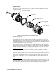
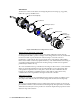
Oxygen Detector The detector consists of the oxygen sensor, the detector housing body, detector housing cap, and cap gasket. Detector Housing Body Cap Gasket Plug-in Oxygen Sensor Detector Housing Cap Flame Arrestor Guard Figure 2: Oxygen Detector Component Location Detector Housing Body The detector housing body protects the electronic components within the housing. Use the mounting threads at the top of the housing to screw the oxygen detector into the 3/4” NPT hub on the bottom of the junction box.
CO Detector The detector consists of the CO sensor, charcoal filter with rubber boot, detector housing body, detector housing cap, and cap gasket. Detector Housing Body Cap Gasket Plug-In CO Sensor Rubber Boot With Charcoal Filter Detector Housing Cap Flame Arrestor Guard Figure 3: CO Detector Component Location Detector Housing, Housing Cap, & Cap Gasket The detector housing body protects the sensing components within the housing.
H2S Detector The detector consists of the detector housing body, detector housing cap, cap gasket, rubber boot, spacer, and H2S sensor. Detector Housing Body Cap Gasket H2S Plug-in Sensor Spacer Rubber Boot Detector Housing Cap Flame Arrestor Guard Figure 4: H2S Detector Component Location Detector Housing, Housing Cap, & Cap Gasket The detector housing protects the sensing components within the housing. Use the mounting threads at the top of the housing to screw the H2S detector into a 3/4” NPT hub.
Junction Box Use the junction box to install the multi-point detector at a mounting site that is remote from the controller. The junction box protects the terminal strip and wiring connections made to the terminal strip. Use the top 3/4’’ conduit hub to connect wiring from the terminal strip to the controller. Use the cover on the front of the junction box to access the interior of the junction box. The detectors and terminal strip are factory installed in the junction box.
.20 DIA X .45 Slot,(2X) ,mounting 7.75 3/4 NPT HUBS (4X) 3.15 2.40 3.11 .25 1.25 8.24 max. 3.00 H2S Detector LEL(CH4 IR) Detector 3.00 1.
.20 DIA X .45 Slot,(2X) ,mounting 7.75 3/4 NPT HUBS (4X) 3.15 2.40 3.11 .25 1.25 8.24 max. 3.00 CO Detector LEL(CH4 IR) Detector 3.00 1.
.20 DIA X .45 Slot,(2X) ,mounting 7.63 3/4 NPT HUBS (4X) 3.15 2.40 3.11 max. .25 1.25 5.05 max. 3.10 max. 3.00 H2S Detector 3/4" Conduit Plug 3.00 1.
.20 DIA X .45 Slot,(2X) ,mounting 7.63 3/4 NPT HUBS (4X) 3.15 2.40 3.11 .25 1.25 8.24 max. 3.00 CO Detector 3/4" Conduit Plug 3.00 1.
.20 DIA X .45 Slot,(2X) ,mounting 7.63 3/4 NPT HUBS (4X) 3.15 2.40 3.11 .25 1.25 8.24 max. 3/4" Conduit Plug 3.00 LEL(CH4 IR) Detector 3.00 Oxygen Detector Figure 9: Outline and Mounting Dimensions 65-2482RK-05 12 • 65-2482RK Multi Point Detector 1.
.20 DIA X .45 Slot,(2X) ,mounting 7.75 3.15 2.40 3/4 NPT HUBS (4X) 3.11 .25 1.25 8.24 max. 3.00 LEL (CH4 IR) Detector H2S Detector 1.10 3.00 CO Detector Figure 10: Outline and Mounting Dimensions 65-2482RK-06 2. At the mounting site you select, use #10 screws to mount the detector to a vertical surface. CAUTION: Mount the multi-point detector with the detectors facing down (see Figures 5-10).
Wiring the Multi-Point Detector to a Controller WARNING: Always verify that the power source is OFF before you make wiring connections. 1. Turn off the controller. 2. Turn off or unplug power to the controller. 3. Remove the junction box cover from the junction box. WARNING: To maintain the explosion proof classification of the multi-point detector, a conduit seal must be used within 18 inches of the junction box conduit hub used for wiring to the controller. 4.
Red Black Controller H2S Terminals Red White Green Black Controller L EL Terminals White Green Controller O xygen Terminals Terminal Stri p Red Green Black White H2S Detector Wires Oxygen Detector Wires Black Green White Red LEL(CH4 IR) Detector W ires LEL(CH4 IR) Detector Oxygen Detector H2S Detector Figure 11: Wiring the 65-2482RK-01 to a Controller 65-2482RK Multi Point Detector • 15
Red Black Controller CO Terminals Red White Green Black Controller L EL Terminals White Green Controller O xygen Terminals Terminal Stri p Red Green Black White CO Detector Wires Oxygen Detector Wires Black Green White Red LEL(CH4 IR) Detector W ires LEL(CH4 IR) Detector Oxygen Detector CO Detector Figure 12: Wiring a 65-2482RK-02 to a Controller 16 • 65-2482RK Multi Point Detector
Red Black Controller H2S Terminals Red White Green Black Controller L EL Terminals Terminal Stri p Red Black H2S Detector Wires Black Green White Red LEL(CH4 IR) Detector W ires LEL(CH4 IR) Detector H2S Detector Figure 13: Wiring the 65-2482RK-03 to a Controller 65-2482RK Multi Point Detector • 17
Red Black Controller CO Terminals Red White Green Black Controller L EL Terminals Terminal Stri p Red Black CO Detector Wires Black Green White Red LEL(CH4 IR) Detector W ires LEL(CH4 IR) Detector CO Detector Figure 14: Wiring the 65-2482RK-04 to a Controller 18 • 65-2482RK Multi Point Detector
Red White Green Black Controller LEL Terminals White Green Controller OXY Terminals Terminal Strip White Green Oxygen Detector Wires Black Green White Red LEL(CH4 IR) Detector Wires LEL(CH4 IR) Detector Oxygen Detector Figure 15: Wiring the 65-2482RK-05 to a Controller 65-2482RK Multi Point Detector • 19
Red Black Controller H2S Terminals Red White Green Black Controller L EL Terminals Red Black Controller CO Terminals Terminal Stri p Red Black Black Red CO Detector W ires H2S Detector W ires Black Green White Red LEL(CH4 IR) Detector W ires LEL(CH4 IR) Detector H2S Detector CO Detector Figure 16: Wiring the 65-2482RK-06 to a Controller 9. Connect the cable’s drain wire to an available chassis ground at the controller.
Start Up This section describes procedures to start up the multi-point detector and place the detector into normal operation. Introducing Incoming Power 1. Complete the installation procedures described earlier in this manual. 2. Verify that the power wiring to the controller is correct and secure. Refer to the controller operator’s manual. 3. Turn on power to the controller. 4. Turn on the controller. 5. Verify that the controller is on and operating properly.
Maintenance This section describes maintenance procedures. It includes preventive maintenance, troubleshooting, and component replacement procedures. Preventive Maintenance This section describes a preventive maintenance schedule to ensure the optimum performance of the multi-point detector. It includes daily, monthly, and quarterly procedures. Daily At the controller, verify a display reading of: • 0 %LEL for CH4 • 20.
NOTE: Ensure that you are using an appropriate calibration cylinder for the channel you are testing. 5. Use the calibration kit sample tubing to connect the regulator to the calibration cup. Performing the response test 1. Turn the regulator’s on/off knob counterclockwise to open the regulator. Gas will begin to flow. 2. Allow the gas to flow for two minutes, then verify that the reading is within ± 20% of the cylinder gas concentration.
Troubleshooting The troubleshooting guide describes symptoms, probable causes, and recommended action for problems you may encounter with the multi-point detector. NOTE: This troubleshooting guide describes multi-point detector problems only. See the controller operator’s manual for problems you may encounter with the controller. Table 2: Troubleshooting the Multi-Point Detector Condition Symptom(s) Probable Causes Recommended Action Fail Condition Controller indicates a fail condition.
Replacing Components of the Multi-Point Detector This section includes maintenance procedures for the IR LEL CH4 detector, the oxygen detector, the CO detector, and the H2S detector. Replacing the IR LEL CH4 Detector 1. Turn off the controller. 2. Turn off or unplug incoming power to the controller. 3. Remove the junction box cover. 4. Disconnect the detector leads from the terminal block in the junction box. Note the position of the color-coded leads as you remove them. 5.
detector housing. 6. Make sure the cap gasket is in place and screw the detector housing cap back onto the detector housing body. 7. Turn on or plug in power to the controller. 8. Turn on the controller and place into normal operation. CAUTION: Allow the replacement sensor to warm up for 5 minutes before you continue with the next step. 9. Calibrate the detector as described in “Calibration, O2 Detector” on page 32.
CO Detector This section includes a procedure to replace the plug-in sensor, one to replace the charcoal filter, and one to replace the entire detector assembly. In most cases it is not necessary to replace the entire detector assembly. Replacing the Plug-In CO Sensor CAUTION: The sensor contains electrolyte which is a dilute acid. Do not disassemble the sensor when replacing it with a new one. If sensor electrolyte comes in contact with your skin, wash affected area thoroughly with soap and water. 1.
11. Turn on or plug in power to the controller. 12. Turn on the controller and place into normal operation. Replacing the CO Detector NOTE: In most cases, it is only necessary to replace the CO sensor. 1. Turn off the controller. 2. Turn off or unplug power to the controller. 3. Remove the junction box cover. 4. Disconnect the detector leads from the terminal block in the junction box. Note the position of the color-coded leads as you remove them. 5. Unscrew the detector from the junction box hub.
6. Install the spacer and rubber boot onto the replacement sensor’s face. 7. Carefully plug the replacement sensor into the socket pattern that is located in the detector housing. 8. Make sure the cap gasket is in place and screw the detector housing cap onto the detector housing body. 9. Turn on or plug in power to the controller. 10. Turn on the controller. CAUTION: Allow the replacement sensor to warm up for 5 minutes before you continue with the next step. 11.
Calibration Frequency Although there is no particular calibration frequency that is correct for all applications, a calibration frequency of every 3 months is adequate for most multi-point detector applications. Unless experience in a particular application dictates otherwise, RKI Instruments, Inc. recommends a calibration frequency of every 3 months for the oxygen, H2S, and CO detectors and every 6 months for the infrared LEL detector.
NOTE: RKI controllers have a minimum hold feature for zero adjustment and a peak hold feature for span adjustment. Because of this, the instructions call for turning off the gas to a detector before making adjustments. Setting the Zero Reading 1. Follow the directions in the controller operator’s manual for setting the zero reading. 2. When the instructions call for applying zero air to the detector, turn the regulator’s on/off knob counterclockwise to open it. Gas will begin to flow. 3.
4. Store the components of the calibration kit in a safe and convenient place. Calibration, O2 Detector This section describes how to calibrate the oxygen detector on the multi-point detector. It includes procedures to prepare for calibration, set the fresh air reading, set the zero reading, and return to normal operation. It describes calibration using a calibration kit that includes a calibration cup, calibration gas, sample tubing, and a fixed flow regulator with an on/off knob. RKI Instruments, Inc.
5. Set the fresh air reading according to the controller operator’s manual. 6. Unscrew the regulator from the zero air calibration cylinder. Leave the sample tubing connected to the regulator and the calibration cup. Setting the Zero Reading 1. Screw the regulator into the 100% nitrogen calibration gas cylinder. Make sure the regulator is off. It is off when the on/off knob is turned all the way clockwise. 2. Follow the directions in the controller operator’s manual for setting the zero reading. 3.
Parts List Table 5 lists replacement parts and accessories for the multi-point detector. Table 3: Parts List Part Number Description 06-1248RK-03 Calibration kit sample tubing, 3 ft.
Table 3: Parts List Part Number Description 81-0078RK-03 Calibration cylinder, 100% nitrogen, 103 liter 81-0090RK Calibration cylinder, 3-gas mix (CH4/ CO/ O2), 17 liter steel 81-0090RK-01 Calibration cylinder, 3-gas mix (CH4/ CO/ O2), 34 liter steel 81-0090RK-03 Calibration cylinder, 3-gas mix (CH4/ CO/ O2), 103 liter steel 81-0151RK-02 Calibration cylinder, 25 ppm H2S in nitrogen, 58 liter aluminum 81-0151RK-04 Calibration cylinder 25 ppm H2S in nitrogen, 34 liter aluminum 81-0160RK-02 Cali