65-2485RK-02 Multi Point Detector Operator’s Manual Part Number: 71-0237RK Revision: 0 Released: 7/18/14 RKI Instruments, Inc. www.rkiinstruments.
WARNING Read and understand this instruction manual before operating detector. Improper use of the detector could result in bodily harm or death. Periodic calibration and maintenance of the detector is essential for proper operation and correct readings. Please calibrate and maintain this detector regularly! Frequency of calibration depends upon the type of use you have and the sensor types.
Product Warranty RKI Instruments, Inc. warrants gas alarm equipment sold by us to be free from defects in materials, workmanship, and performance for a period of one year from date of shipment from RKI Instruments, Inc. Any parts found defective within that period will be repaired or replaced, at our option, free of charge.
Table of Contents Overview . . . . . . . . . . . . . . . . . . . . . . . . . . . . . . . . . . . . . . . . . . . . . . . . . . . . . . . . . . . . . . . . . . . 1 Specifications. . . . . . . . . . . . . . . . . . . . . . . . . . . . . . . . . . . . . . . . . . . . . . . . . . . . . . . . . . . . . . . . 1 Description . . . . . . . . . . . . . . . . . . . . . . . . . . . . . . . . . . . . . . . . . . . . . . . . . . . . . . . . . . . . . . . . . . 2 Detectors. . . . . . . . . . . . . . . . . . . . . . . . .
Overview This manual describes the 65-2485RK-02 multi point direct connect detector. This manual also describes how to install, start up, maintain, and calibrate the detector when it is used with a gas monitoring controller. A parts list at the end of this manual lists replacement parts and accessories for the detector. Specifications WARNING: Do not use this product in a manner not specified in this instruction manual. Table 1 lists specifications for the multi-point detector.
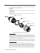
Description This section describes the multi-point detector. It consists of the detectors, the terminal strips, the conduit seal, and the junction boxes. Detectors This section describes the components of the various detectors that are used with the 65-2485RK-02. Oxygen Detector The detector consists of the oxygen sensor, the detector housing body, detector housing cap, and cap gasket.
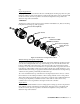
cap. Plug-in Oxygen Sensor The plug-in sensor is secured in the detector assembly by the housing cap. It has two pins that mate with the sockets in the detector housing body. Through a series of chemical and electrical reactions, the sensor produces an electrical output that corresponds to the detection range of the transmitter. CO Detector The detector consists of the CO sensor, charcoal filter with rubber boot, detector housing body, detector housing cap, and cap gasket.
Charcoal Filter The disc-shaped charcoal filter is secured to the face of the CO sensor with a rubber boot. The charcoal filter prevents interference gases (hydrogen sulfide [H2S] and certain hydrocarbons) from producing false CO readings. H2S Detector The detector consists of the detector housing body, detector housing cap, cap gasket, rubber boot, spacer, and H2S sensor.
pins that mate with the sockets in the detector housing body. Through a series of chemical and electrical reactions, the sensor produces an electrical output that is proportional to the detection range of the detector. Junction Box Use the junction box to install the multi-point detector at a mounting site that is remote from the controller. The junction box protects the terminal strip and wiring connections made to the terminal strip.
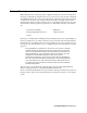
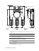
.20 DIA X .45 Slot,(2X) ,mounting 7.75 3/4 INCH NPT HUBS (4X) 3.15 2.40 3.11 .25 1.25 8.24 max. 3.00 H2S Detector 3.00 CO Detector 1.10 Oxygen Detector Figure 4: Outline & Mounting Dimensions 65-2485RK-02 2. At the mounting site you select, use #10 screws to mount the detector to a vertical surface. CAUTION: Mount the multi-point detector with the detectors facing down (see Figure 4).
3. Remove the junction box cover from the junction box. WARNING: To maintain the explosion proof classification of the multi-point detector, a conduit seal must be used within 18 inches of the junction box conduit hub used for wiring to the controller. 4. Guide a six-conductor, shielded cable, or six wires in conduit through the top conduit hub of the junction box.
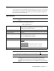
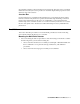
Red Black Controller H2S Terminals Red Black Controller CO Terminals White Green Controller O xygen Terminals Terminal Stri p Red Green Black White H2S Detector Wires Oxygen Detector Wires Black Red CO Detector Wires Oxygen Detector H2S Detector CO Detector Figure 5: Wiring the 65-2485RK-02 to a Controller 9. Connect the cable’s drain wire to an available chassis ground at the controller. RKI controllers typically have a ground stud that can be used to ground the cable’s drain wire.
Start Up This section describes procedures to start up the multi-point detector and place the detector into normal operation. Introducing Incoming Power 1. Complete the installation procedures described earlier in this manual. 2. Verify that the power wiring to the controller is correct and secure. Refer to the controller operator’s manual. 3. Turn on power to the controller. 4. Turn on the controller. 5. Verify that the controller is on and operating properly.
Maintenance This section describes maintenance procedures. It includes preventive maintenance, troubleshooting, and component replacement procedures. Preventive Maintenance This section describes a preventive maintenance schedule to ensure the optimum performance of the multi-point detector. It includes daily, monthly, and quarterly procedures. Daily At the controller, verify a display reading of: • 20.9% for oxygen • 0 ppm for CO or H2S Investigate significant changes in the display reading.
Performing the response test 1. Turn the regulator’s on/off knob counterclockwise to open the regulator. Gas will begin to flow. 2. Allow the gas to flow for two minutes, then verify that the reading is within ± 20% of the cylinder gas concentration. NOTE: If the reading is not within ± 20% of the correct response reading, calibrate the detector as described in the Calibration section of this manual. 3. Turn the regulator’s on/off knob clockwise to close the regulator. 4.
Condition Slow or No Response/ Difficult or Unable to Calibrate Symptom(s) Probable Causes Recommended Action • Detector responds slowly or does not respond to response test. • Unable to accurately set the zero or response reading during calibration. • Detector requires frequent calibration. • The calibration cylinder is low, out-dated, or defective. • The flame arrestor in the CO, O2, or H2S detector housing cap is wet or clogged with dirt or other particulates.
8. Turn on the controller and place into normal operation. CAUTION: Allow the replacement sensor to warm up for 5 minutes before you continue with the next step. 9. Calibrate the detector as described in “Calibration, O2 Detector” on page 18. Replacing the Oxygen Detector NOTE: In most cases, it is only necessary to replace the oxygen sensor. 1. Turn off the controller. 2. Turn off or unplug incoming power to the controller. 3. Remove the junction box cover from the junction box. 4.
3. Unscrew the detector housing cap from the detector housing body. Make sure not to lose the cap gasket. 4. Unplug and remove the CO sensor with the boot and charcoal filter attached. 5. Remove the rubber boot and charcoal filter from the old sensor. 6. Install the rubber boot with charcoal filter onto the replacement sensor’s face. 7. Carefully plug the replacement sensor into the four-socket pattern that is located in the detector housing. 8.
5. Unscrew the detector from the junction box hub. 6. Guide the detector leads of the replacement detector through the junction box hub then screw the mounting threads of the detector into the hub. If necessary for environmental conditions, apply thread sealant or teflon tape to the hub and/or detector threads to seal them. 7. Connect the detector leads to the terminal block the same way the old detector was wired.
11. Calibrate the detector as described in “Calibration, H2S and CO Detectors” on page 17. Replacing the H2S Detector NOTE: In most cases, it is only necessary to replace the H2S sensor. 1. Turn off the controller. 2. Turn off or unplug power to the controller. 3. Remove the junction box cover from the junction box. 4. Disconnect the detector leads from the terminal block in the junction box. Note the position of the color-coded leads as you remove them. 5.
Calibration, H2S and CO Detectors This section describes how to calibrate the H2S and CO detectors on the multi-point detector. It includes procedures to prepare for calibration, set the zero reading, set the response reading, and return to normal operation. It describes calibration using a calibration kit that includes a calibration cup, calibration gas, sample tubing, and a fixed flow regulator with an on/off knob. RKI Instruments, Inc. recommends using a 0.5 LPM (liters per minute) fixed flow regulator.
Setting the Response Reading 1. Screw the regulator into the calibration gas cylinder. Make sure the regulator is off. It is off when the on/off knob is turned all the way clockwise. NOTE: Ensure that you are using an appropriate calibration cylinder for the channel you are calibrating. 2. Follow the directions in the controller operator’s manual for setting the response reading (span). 3.
Preparing for Calibration WARNING: Do not remove the junction box cover or detector housing cap while the circuits are energized unless the area is determined to be non-hazardous. Keep the junction box cover and detector housing cap tightly closed during operation. 1. Screw the calibration cup onto the bottom of the oxygen detector. 2. Screw the regulator into the zero air calibration cylinder. Make sure the regulator is off. It is off when the on/off knob is turned all the way clockwise.
Returning to Normal Operation 1. Unscrew the calibration cup from the oxygen detector. NOTE: For convenience, leave regulator and calibration cup connected by the sample tubing. 2. When the controller display reading rises above the alarm points, return the controller to normal operation. NOTE: If you do not allow the gas reading to rise above the alarm points, then unwanted alarms may occur. 3. Verify that the controller display reading increases and stabilizes at 20.9% oxygen. 4.
Table 3: Parts List Part Number Description 81-0078RK-01 Calibration cylinder, 100% nitrogen, 34 liter 81-0078RK-03 Calibration cylinder, 100% nitrogen, 103 liter 81-0151RK-02 Calibration cylinder, 25 ppm H2S in nitrogen, 58 liter aluminum 81-0151RK-04 Calibration cylinder 25 ppm H2S in nitrogen, 34 liter aluminum 81-0154RK-02 Calibration cylinder, 4-gas mix (CH4/ O2/ CO/ H2S), 58 liter aluminum 81-0154RK-04 Calibration cylinder, 4-gas mix (CH4/ O2/ CO/ H2S), 34 liter aluminum 81-1050RK Regul