65-2495RK/65-2498RK Hydrogen Sulfide Detector Operator’s Manual Part Number: 71-0155RK Revision: P1 Released: 8/17/09 www.rkiinstruments.
Product Warranty RKI Instruments, Inc., warrants gas alarm equipment sold by us to be free from defects in materials, workmanship, and performance for a period of one year from date of shipment from RKI Instruments, Inc. Any parts found defective within that period will be repaired or replaced, at our option, free of charge.
Table of Contents Overview . . . . . . . . . . . . . . . . . . . . . . . . . . . . . . . . . . . . . . . . . . . . . . . . . . . . . . . . . . . . . . . . . . . 4 Specifications. . . . . . . . . . . . . . . . . . . . . . . . . . . . . . . . . . . . . . . . . . . . . . . . . . . . . . . . . . . . . . . . 4 Description . . . . . . . . . . . . . . . . . . . . . . . . . . . . . . . . . . . . . . . . . . . . . . . . . . . . . . . . . . . . . . . . . . 5 65-2495RK H2S Detector . . . . . . . . . . . . . . . . . .
Overview This manual describes the 65-2498RK hydrogen sulfide (H2S) detector. This manual also describes how to install, start up, maintain, and calibrate the H2S detector when used with a gas monitoring controller. A parts list at the end of this manual lists replacement parts and accessories for the H2S detector. The 65-2498RK H2S detector includes the 65-2495K H2S detector and a junction box.
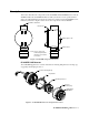
Description This section describes the components of the 65-2495RK and 65-2498RK detectors. The 652498RK includes the 65-2495RK H2S detector and a junction box. A two point terminal strip is provided inside the junction box for detector connections. The 65-2495RK does not include a junction box. Figure 1 below shows the components of the 65-2498RK. 3/4 NPT Conduit Hub Junction Box Rubber Spacer, 3X H S Detector 2 Note: There is a two point terminal strip inside the junction box for detector connections.
Detector Housing Body The detector housing body protects the electronic components within the housing. Use the mounting threads at the top of the housing to screw the H2S detector into a 3/4” NPT hub. Two wires extend from the top of the detector housing body. Use these wires to connect the detector to a controller. One of the wires is black and one of the wires is red. The housing body includes a four-socket pattern at the bottom of the housing body. The plug-in sensor mates to this socket pattern.
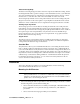
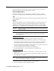
NOTE: If your application does not require a specific mounting site, mount the detector at approximately breathing level. 2.70 3/4 NPT Conduit Hub 7.30 + .25 .38 .75 3/4" NPT Rubber Spacer, 3X 3.65 .75 6.80 Max 1.32 H2S Detector Junction Box Ø 1.75 1 1/2-20 Thread for Calibration Cup 1 1/2-20 Thread for Calibration Cup 65-2495RK 65-2498RK Figure 3: Outline & Mounting Dimensions, 65-2495RK & 65-2498RK 2.
5. Guide a two-conductor, shielded cable or two wires in conduit through the unused conduit hub of the junction box. Use appropriate conduit fittings and construction technique for the environmental rating of the junction box. The junction box is rated NEMA 4X. 6. Connect the two wires to the detector using the terminal block. CAUTION: If using shielded cable, leave the drain wire insulated and disconnected at the detector. You will connect the opposite end of the cable’s drain wire at the controller.
Start Up This section describes procedures to start up the H2S detector and place the detector into normal operation. Introducing Incoming Power 1. Complete the installation procedures described earlier in this manual. 2. Verify that the power wiring to the controller is correct and secure. Refer to the controller operator’s manual. 3. Turn on or plug in the incoming power, then turn on the controller. 4. Verify that the controller is on and operating properly.
Maintenance This section describes maintenance procedures. It includes preventive maintenance, troubleshooting, and component replacement procedures. Preventive Maintenance This section describes a preventive maintenance schedule to ensure the optimum performance of the H2S detector. It includes daily, monthly, and quarterly procedures. Daily Verify a display reading of 0 ppm at the controller. Investigate significant changes in the display reading.
5. Unscrew the calibration cup from the H2S detector. Make sure that you do not loosen the detector housing cap when you unscrew the calibration cup. 6. When the controller display reading falls below the alarm setpoints, return the controller to normal operation. Quarterly Calibrate the H2S detector as described in “Calibration” on page 14. Troubleshooting The troubleshooting guide describes symptoms, probable causes, and recommended action for problems you may encounter with the H2S detector.
Probable causes • The plug-in sensor has been replaced and the shorting jumper has not been removed. • The calibration cylinder is low, out-dated, or defective. • The incorrect calibration cup or regulator is being used. • The membrane on the detector housing cap is blocked with dirt or some other particulate contamination. • The detector is malfunctioning. Recommended action 1. Confirm that the shorting jumper on the plug-in sensor pins has been removed. 2.
6. Carefully plug the replacement sensor into the four-socket pattern that is located in the detector housing body. WARNING: You must replace the plug-in sensor with the same type of sensor that is installed. A detector cannot be converted from one type of detector to another by using a different plug-in sensor. For example, if you are replacing an H2S sensor, you must replace it with an H2S sensor. 7.
color-coded leads as you remove them. 5. Unscrew the detector from the controller conduit hub or junction box conduit hub. 6. Guide the detector leads of the replacement detector through the controller conduit hub or junction box conduit hub, then screw the mounting threads of the detector into the hub. If necessary for environmental conditions, apply thread sealant or teflon tape to the hub and/or detector threads to seal them. 7.
WARNING: Not using the recommended calibration cup and sample flowrate will result in an inaccurate calibration. See“Parts List” on page 16 for the required calibration cup and regulator. Preparing for Calibration 1. Screw the calibration cup onto the bottom of the H2S detector. 2. Screw the regulator into the zero air calibration cylinder. Make sure the regulator is off. It is off when the on/off knob is turned all the way clockwise. 3.
the detector housing cap when you unscrew the calibration cup. NOTE: For convenience, leave the regulator and calibration cup connected by the sample tubing. 9. Allow about 45 seconds for the gas reading to decrease below the alarm points and then return the controller to normal operation. NOTE: If you do not allow the gas reading to decrease below the alarm points, then unwanted alarms may occur. 10. Verify that the controller display reading decreases and stabilizes at 0 ppm. 11.