65-2513RK Oxygen Transmitter Operator’s Manual Part Number: 71-0111RK Revision: A Released: 3/1/11 www.rkiinstruments.
WARNING Read and understand this instruction manual before operating detector. Improper use of the detector could result in bodily harm or death. Periodic calibration and maintenance of the detector is essential for proper operation and correct readings. Please calibrate and maintain this detector regularly! Frequency of calibration depends upon the type of use you have and the sensor types.
Product Warranty RKI Instruments, Inc. warrants gas alarm equipment sold by us to be free from defects in materials, workmanship, and performance for a period of one year from date of shipment from RKI Instruments, Inc. Any parts found defective within that period will be repaired or replaced, at our option, free of charge.
Table of Contents Overview . . . . . . . . . . . . . . . . . . . . . . . . . . . . . . . . . . . . . . . . . . . . . . . . . . . . . . . . . . . . . . . . . . . 1 Specifications. . . . . . . . . . . . . . . . . . . . . . . . . . . . . . . . . . . . . . . . . . . . . . . . . . . . . . . . . . . . . . . . 1 Description . . . . . . . . . . . . . . . . . . . . . . . . . . . . . . . . . . . . . . . . . . . . . . . . . . . . . . . . . . . . . . . . . . 2 Oxygen Detector . . . . . . . . . . . . . . . . . . . . . .
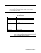
Overview This instruction manual describes the oxygen transmitter. This manual also describes how to install, start up, configure, maintain, and calibrate the transmitter when using it with a gas monitoring controller. A parts list at the end of this manual lists replacement parts and accessories for the oxygen transmitter. See the controller operator’s manual for information specific to the controller. Specifications Table 1 lists specifications for the oxygen transmitter.
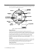
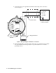
Description This section describes the components of the oxygen transmitter. The transmitter consists of the oxygen detector, amplifier, and junction box. % $ $ (factory-set) " )* $ - &' ( &+ POWER/SIG !# $ " !" SENSOR " - .
The amplifier included with the oxygen transmitter is designed for use with RKI’s oxygen and toxic gas transmitters. The amplifier type selector determines for which transmitter the amplifier is intended. For oxygen transmitters, a jumper block is installed over the OXYGEN selector (see Figure 1). Detector Terminal Strip The detector terminal strip is the four-point terminal strip near the bottom of the amplifier. Use the detector terminal strip to connect the oxygen detector to the amplifier.
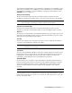
Installation This section describes procedures to mount the oxygen transmitter in the monitoring environment and wire the transmitter to a controller. Mounting the Oxygen Transmitter 1. Select a mounting site that is representative of the monitoring environment. Consider the following when you select the mounting site. • Select a site where the transmitter is not likely to be bumped or disturbed. Make sure there is sufficient room to perform start-up, maintenance, and calibration procedures.
Wiring the Oxygen Transmitter to a Controller WARNING: Always verify that the controller is off and power to the controller is off before you make wiring connections. 1. Turn off the controller. 2. Turn off power to the controller. 3. Remove the junction box cover. 4. Verify that the detector leads are wired to the amplifier’s detector terminal strip. If necessary, connect the leads to the detector terminal strip as shown in Figure 3. 5.
11. Connect the wires to the applicable transmitter terminal strip at the controller as shown in Figure 3. 4 - 20 mA In (FB or S) + 24 VDC Cable Shield TP - Not Used FB + 4/20 24V Controller Transmitter Terminals,Typical TP + POWER/SIG ZERO SPAN SENSOR OXYGEN NOT USED OXY W G Green White Amplifier Type Selector, Set to OXYGEN Oxygen Detector Figure 3: Wiring the Oxygen Transmitter to a Controller 12.
Start Up This section describes procedures to start up the oxygen transmitter and place the transmitter into normal operation with a controller. Introducing Incoming Power 1. Complete the installation procedures described earlier in this manual. 2. Verify that the power wiring to the controller is correct and secure. Refer to the controller operator’s manual. 3. Turn on or plug in the incoming power, then turn on the controller. 4. Verify that the controller is on and operating properly.
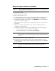
16. Secure the junction box cover to the junction box. Maintenance This section describes maintenance procedures. It includes preventive maintenance, troubleshooting, and component replacement procedures. Preventive Maintenance This section describes a preventive maintenance schedule to ensure the optimum performance of the oxygen transmitter. It includes daily, monthly, and quarterly procedures. Daily Verify a display reading of 20.9% oxygen at the controller.
Troubleshooting The troubleshooting guide describes symptoms, probable causes, and recommended action for problems you may encounter with the oxygen transmitter. NOTE: This troubleshooting guide describes transmitter problems only. See the controller operator’s manual for problems you may encounter with the controller. Table 2:Troubleshooting the Oxygen Transmitter Condition Symptom(s) Probable Causes Recommended Action Fail Condition • Controller indicates a fail condition.
7. Connect the detector leads to the amplifier’s detector terminal strip as shown in Table 3 below and Figure 3 on page 6 of this manual. Table 3:Reconnecting the Oxygen Detector to the Amplifier Detector Lead Detector Terminal Strip White OXY W Green OXY G 8. Turn on power to the controller 9. Turn on the controller. 10. Calibrate the replacement detector as described in “Calibration” on page 12 of this manual. Replacing the Amplifier 1. Turn off the controller 2.
11. Reconnect the detector leads to the amplifier’s detector terminal strip as shown in Table 5 below and Figure 3 on page 6 of this manual. Table 5:Reconnecting the Oxygen Detector to the Amplifier Detector Lead Detector Terminal Strip White OXY W Green OXY G 12. Turn on power to the controller 13. Turn on the controller. 14. Calibrate the oxygen transmitter as described in “Calibration” on page 12 of this manual.
Calibration This section describes how to calibrate the oxygen transmitter. It includes procedures to prepare for calibration, set the fresh air reading, set the zero reading, and return to normal operation. It describes the test using a calibration kit that includes a calibration cup, calibration gas, sample tubing, and a fixed flow regulator with an on/off knob. RKI Instruments, Inc. recommends using a 0.5 LPM (liters per minute) fixed flow regulator.
5. Turn the regulator knob clockwise to close the regulator. 6. Unscrew the regulator from the calibration cylinder. 7. Unscrew the calibration cup from the oxygen detector. NOTE: For convenience, leave the components of the calibration kit connected by the sample tubing. Returning to Normal Operation 1. Remove the voltmeter leads from the amplifier test points. 2. Secure the junction box cover to the junction box. 3.