65-2515RK Oxygen Detector Operator’s Manual Part Number: 71-0137RK Revision: 0 Released: 3/1/11 www.rkiinstruments.
WARNING Read and understand this instruction manual before operating detector. Improper use of the detector could result in bodily harm or death. Periodic calibration and maintenance of the detector is essential for proper operation and correct readings. Please calibrate and maintain this detector regularly! Frequency of calibration depends upon the type of use you have and the sensor types.
Product Warranty RKI Instruments, Inc. warrants gas alarm equipment sold by us to be free from defects in materials, workmanship, and performance for a period of one year from date of shipment from RKI Instruments, Inc. Any parts found defective within that period will be repaired or replaced, at our option, free of charge.
Table of Contents Overview . . . . . . . . . . . . . . . . . . . . . . . . . . . . . . . . . . . . . . . . . . . . . . . . . . . . . . . . . . . . . . . . . . . 1 Specifications. . . . . . . . . . . . . . . . . . . . . . . . . . . . . . . . . . . . . . . . . . . . . . . . . . . . . . . . . . . . . . . . 1 Description . . . . . . . . . . . . . . . . . . . . . . . . . . . . . . . . . . . . . . . . . . . . . . . . . . . . . . . . . . . . . . . . . . 2 Oxygen Detector . . . . . . . . . . . . . . . . . . . . . .
Overview This manual describes the 65-2515RK oxygen detector (internal amplifier type). This manual also describes how to install, start up, maintain, and calibrate the detector when used with a gas monitoring controller. A parts list at the end of this manual lists replacement parts and accessories for the oxygen detector. Specifications Table 1 lists specifications for the 65-2515RK oxygen detector. Table 1: 65-2515RK Specifications Target Gas Oxygen Sampling Method Diffusion Detection Range 0 - 25.
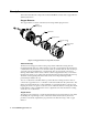
Description This section describes the components of the 65-2515RK. It consists of the oxygen detector and the junction box Oxygen Detector The oxygen detector consists of the detector housing and the plug-in sensor. Detector Housing Body Cap Gasket Oxygen Sensor Detector Housing Cap Flame Arrestor Guard Figure 1: Oxygen Detector Component Location Detector Housing The detector housing protects the sensing components within the housing.
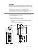
Junction Box The junction box allows you to install the oxygen detector at a mounting site that is remote from a controller and it protects the detector wiring connections. Two conduit hubs allow you to mount the oxygen detector to the junction box and route the wiring from the detector to a controller.
NOTE: The oxygen detector in the 65-2515RK is normally provided with an Adalet XIHSCFC3 junction box rated explosion proof for Class I, Groups B, C, and D. This combination is shown in Figure 2 above. Any junction box with an internal volume less than or equal to 69 cubic inches and rated explosion proof for Class I, Groups B, C, and D may be used for this detector. 2. At the mounting site you select, hang or mount the junction box with the detector facing down (see Figure 2).
WARNING: To maintain the explosion proof classification of the oxygen detector/ junction box combination, a conduit seal must be used within 18 inches of the junction box conduit hub used for wiring to the controller. 5. Connect the wires to the terminals opposite the detector leads using the terminal strip in the junction box. CAUTION: If using shielded cable, leave the drain wire insulated and disconnected at the detector. You will connect the opposite end of the cable’s drain wire at the controller. 6.
NOTE: If you can verify that the detector is in a fresh air environment (environment known to be of normal oxygen content and free of toxic and combustible gases), it is not necessary to apply zero air when verifying or setting the fresh air reading. The procedure below describes applying zero air using a calibration kit that includes a calibration cup, calibration gas, sample tubing, and a fixed flow regulator with an on/off knob. RKI Instruments, Inc. recommends using a 0.
NOTE: Performing a response test on the oxygen detector may cause alarms. Be sure to put the controller into its calibration program or disable external alarms before performing this test. 1. Place the controller into its calibration program or disable external alarms. 2. Verify that the controller display reading is 20.9% oxygen. If the controller reading is not 20.9% oxygen, set the fresh air reading, then continue this procedure.
Troubleshooting The troubleshooting guide describes symptoms, probable causes, and recommended action for problems you may encounter with the oxygen detector. NOTE: This troubleshooting guide describes detector problems only. See the controller operator’s manual for problems you may encounter with the controller. Table 2:Troubleshooting the Oxygen Detector Condition Symptom(s) Probable Causes Recommended Action Fail Condition • Controller indicates a fail condition.
8. Turn on the controller. CAUTION: Allow the replacement sensor to warm up for 5 minutes before you continue with the next step. 9. Calibrate the replacement sensor as described in “Calibration” on page 10. Replacing the Oxygen Detector NOTE: In most cases, it is only necessary to replace the plug-in oxygen sensor. 1. Turn off the controller. 2. Turn off or unplug incoming power to the controller. 3. Remove the junction box cover. 4.
Calibration This section describes how to calibrate the oxygen detector. It includes procedures to prepare for calibration, set the fresh air reading, set the zero reading, and return to normal operation. It describes calibration using a calibration kit that includes a calibration cup, calibration gas, sample tubing, and a fixed flow regulator with an on/off knob. RKI Instruments, Inc. recommends using a 0.5 LPM (liters per minute) fixed flow regulator.
7. Unscrew the regulator from the cylinder. 8. Remove the calibration cup from the detector. For convenience, leave the calibration cup and regulator connected by the sample tubing. Returning to Normal Operation 1. Allow about 45 seconds for the oxygen reading to increase above the decreasing alarm point and return the controller to normal operation. NOTE: If you do not allow the oxygen reading to increase above the decreasing alarm point, then unwanted alarms may occur. 2.