Beacon 200 Gas Monitor Operator’s Manual Part Number: 71-0059RK Revision: D Released: 1/15/14 www.rkiinstruments.
Product Warranty RKI Instruments, Inc., warrants gas alarm equipment sold by us to be free from defects in materials, workmanship, and performance for a period of one year from date of shipment from RKI Instruments, Inc. Any parts found defective within that period will be repaired or replaced, at our option, free of charge.
Table of Contents Chapter 1: Introduction . . . . . . . . . . . . . . . . . . . . . . . . . . . . . . . . . . . . . . . . . . . . . . . . . 5 Overview . . . . . . . . . . . . . . . . . . . . . . . . . . . . . . . . . . . . . . . . . . . . . . . . . . . . . . . . 5 About the Beacon 200 Gas Monitor . . . . . . . . . . . . . . . . . . . . . . . . . . . . . . . . . . . 5 About this Manual . . . . . . . . . . . . . . . . . . . . . . . . . . . . . . . . . . . . . . . . . . . . . . . . . 6 Specifications . . . . .
Chapter 6: Input Setup Program. . . . . . . . . . . . . . . . . . . . . . . . . . . . . . . . . . . . . . . . . 40 Overview . . . . . . . . . . . . . . . . . . . . . . . . . . . . . . . . . . . . . . . . . . . . . . . . . . . . . . . 40 Setting Up a New Channel or Changing an Existing Channel . . . . . . . . . . . . . . 41 Chapter 7: Maintenance . . . . . . . . . . . . . . . . . . . . . . . . . . . . . . . . . . . . . . . . . . . . . . . 44 Overview . . . . . . . . . . . . . . . . . . . . . . . . . . . . .
Chapter 1: Introduction Overview This chapter briefly describes the Beacon 200 Gas Monitor. This chapter also describes the Beacon 200 Gas Monitor Operator’s Manual (this document). Table 1 at the end of this chapter lists the specifications for the Beacon 200. About the Beacon 200 Gas Monitor The Beacon 200 is a fixed-mounted, continuous-monitoring gas detection instrument. This gas monitor is capable of detecting gas at up to two locations.
About this Manual The Beacon 200 Gas Monitor Operator’s Manual is organized as follows: • Chapters 1 through 6 describe components of the Beacon 200 and procedures to install, start up, operate, and maintain the Beacon 200. The Beacon 200 Gas Monitor Operator’s Manual uses the following conventions for notes, cautions, and warnings. NOTE: Describes additional or critical information. CAUTION: Describes potential damage to equipment. WARNING: Describes potential danger that can result in injury or death.
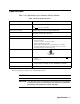
Specifications Table 1 lists specifications for the Beacon 200 Gas Monitor. Table 1: Beacon 200 Specifications Description Specification Input Power 115/220V ~ ±10%, 50/60Hz, 0.5/0.3A1 or 24 V +10% -8%, 0.6A VDC Construction (housing) Fiberglass/polyester with lexan window (NEMA 4X) Dimensions 10.5 in. H x 8.5 in. W x 6.25 in. D (267 mm H x 216 mm W x 158 mm D) Weight 8 lbs. Environmental Conditions • • • • • • • For indoor or outdoor locations (Type 4X) 2000m max.
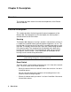
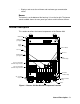
Chapter 2: Description Overview This chapter describes external and internal components of the Beacon 200 Gas Monitor. External Description This section describes the housing and all external components of the Beacon 200. For the purposes of this description, the housing door is considered the front of the monitor. Housing The Beacon 200’s fiberglass housing is weather- and corrosion-resistant. It is suitable for installation where general purpose equipment is in use.
• Displays and resets the minimum and maximum gas concentration values. Buzzer The buzzer is on the bottom of the housing. It is on the far right. The buzzer sounds audible alarms to warn you of gas alarms and instrument failures. Internal Description This section describes the internal components of the Beacon 200.
Display Printed Circuit Board (PCB) The display PCB is mounted to the power supply mounting plate which is in turn mounted to the main PCB. The power supply mounting plate and main PCB are described below. The display PCB includes the display, the status lights, and the program buttons. Display The display simultaneously indicates the channel number, current gas reading, measuring unit, and target gas of all active channels.
Status Lights The Beacon 200 includes four status lights that indicate the current status of the monitor. The status lights are to the left and right of the display (see Figure 2). • Pilot Light. The pilot light is on when the Beacon 200 is receiving incoming power. • Fail Light. The fail light turns on when the Beacon 200 is experiencing a fail condition. A fail condition can be caused by a failure within the Beacon 200 or detector head(s) wired to the Beacon 200.
Main PCB The main PCB is mounted inside the housing. The power supply mounting plate is mounted to the main PCB with four standoffs and the display PCB is mounted to the power supply mounting plate with four standoffs. The main PCB includes the terminal strips, relays, fuses, and power switch. Terminal Strips The Beacon 200 includes four terminal strips for external wiring connections. See “Wiring the Beacon 200 Gas Monitor” for detailed wiring procedures. • Detector/Transmitter Terminal Strips.
• AC In Terminal Strip. The AC in terminal strip is a 3-point terminal strip located above the controller terminal strip (see Figure 1). It facilitates wiring from the AC power source. Table 4 lists the function of each terminal. Table 4: Terminal Assignments for the AC In Terminal Strip Terminal Connects to: LINE Hot wire from AC power source. NEUT Neutral wire from AC power source. GND Earth ground Relays The Beacon 200 includes four channel relays (two per channel) and three common relays.
. Channel 2, Alarm 2 Common Alarm 1 Channel 2, Alarm 1 Common Alarm 2 Channel 1, Alarm 2 Common Fail Channel 1, Alarm 1 K1 K2 K3 K4 K5 K6 K7 Figure 3. Beacon 200 Channel Relay Allocation NOTE: The alarm 2 channel relays may be set to operate as individual channel fail relays. See the Configure Channel Settings section of Chapter 5 for instructions. • Common relays. The three common relays, alarm 1, alarm 2, and fail, are to the left of the controller terminal strip (see Figure 1).
Power Switch The power switch is located above the relays and in between the AC and DC fuses (see Figure 1). The power switch turns the incoming AC power source on and off at the Beacon 200. When the switch is up, the power switch is on. NOTE: The DC power input has no on/off switch and is not affected by the position of this switch. Power Supply The power supply is mounted to the power supply mounting plate which is located behind the display PCB.
Chapter 3: Installation and Start Up Overview This chapter describes procedures to mount the Beacon 200 Gas Monitor, make wiring connections to the monitor, and start up the monitor. WARNING: Perform all installation and start-up procedures in a “fresh air” environment (known to be free of combustible gas, toxic gas, and of normal oxygen content). The Beacon 200 is not in operation as a gas monitoring system until the start-up procedure is complete.
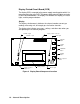
.41 8.50 6.00 Ø .38 x .50 slot, 4X 10.94 Mounting Feet, 4X ALARM 2 FAIL ALARM 1 PILOT 10.50 BEACON 200 GAS MONITOR RESET .80 3/4 " Conduit Hub(3) Figure 4.
AC In Terminal Strip Wiring Typical Detector/Transmitter Terminal Strip Wiring Only one detector or transmitter can be wired to Ch1 or Ch2 at a time. See detector head wiring diagram for specific wiring.
Wiring the Beacon 200 Gas Monitor This section describes procedures to connect the AC power source, DC power source, external alarm(s), recorder, and detector head(s). See Figure 5 for a general wiring diagram of all external wiring to the Beacon 200. WARNING: Make all connections to the Beacon 200 before you plug in or turn on the AC or DC power source. Before you make any wiring adjustments, always verify that all power sources are not live.
CAUTION: Do not route power and detector head wiring through the same conduit hub. The power wiring may disrupt the transmission of the detector head signal to the monitor. 6. Connect the AC wires to the AC power terminal strip as shown in Figure 6. AC In Terminal Strip Line (Hot) Neutral Ground 115 V~ ± 10%, 50/60 Hz (220 V ~ Optional) Figure 6.
CAUTION: When a battery is used as backup power, the Beacon 200 trickle charges the battery. Do not use a non-rechargeable battery as backup power. Use RKI backup battery 49-8102RK or an appropriately rated rechargeable lead acid type battery. 5. Connect the DC wires to the controller terminal strip as shown in Figure 7. Controller Terminal Strip 24 VDC ± 2.5 VDC BAT BAT + + Figure 7.
4. Guide the wiring of the external alarm device through the selected conduit hub on the bottom of the Beacon 200 housing. CAUTION: Do not route the external alarm wiring and detector head wiring through the same conduit hub. The external alarm wiring may disrupt the transmission of the detector signal to the Beacon 200. 5. Connect the leads from the external alarm device and power to the alarm terminals as shown in Figure 8.
4. Guide the wiring from the recording device through the selected conduit hub on the Beacon 200. 5. Connect the wires form the recording device to the recorder output terminals as shown in Figure 9. Recording Device #1, 1Kohm Max Impedance Recording Device #2, 1Kohm Max Impedance + + CH1 OUT + CH2 OUT + Figure 9. Recorder Output Wiring Connecting RKI Detector Heads Perform the following procedure to connect an RKI detector head to the Beacon 200. 1.
CAUTION: Do not route power and detector head wiring through the same conduit hub. The power wiring may disrupt the transmission of the detector head’s to the Beacon 200. . Table 5: Wire Size Guidelines for RKI Detector Head Wiring Number of Wires to Controller Max Distance to Controller w/18 Gauge Wire Max Distance to Controller w/16 Gauge Wire Max Distance to Controller w/14 Gauge Wire Direct Connect LEL 4 500 ft. 1,000 ft. 2,000 ft. Direct Connect Oxygen 2 500 ft. 1,000 ft. 2,000 ft.
6. Connect the wires from the transmitter to the appropriate detector/ transmitter terminals. The top detector terminal strip is for channel 1 and the bottom one is for channel 2. See the transmitter instruction manual for controller terminal connections. Figure 10 below illustrates typical transmitter wiring connections. CAUTION: Do not route power and transmitter wiring through the same conduit hub. The power wiring may disrupt the transmission of the transmitter’s signal to the Beacon 200.
Starting Up the Beacon 200 Gas Monitor Perform the following procedure to place the Beacon 200 into normal operation. 1. Complete the mounting and wiring procedures described earlier in this chapter. 2. Complete all installation procedures described in the detector head or user supplied 4 - 20 mA transmitter instruction manual. 3. Verify that all wiring connections are correct and secure and that the Beacon 200’s power switch is in the OFF position. 4.
Chapter 4: Operation Overview This chapter describes the Beacon 200 Gas Monitor in normal operation. This chapter also describes the Beacon 200 in alarm 1, alarm 2, and fail conditions and suggests response to these conditions. Normal Operation Normal operation is defined as follows: • The start-up procedure is complete. • The Beacon 200 is not indicating an alarm 1, alarm 2, or fail condition. • The Beacon 200 is not running the Channel Control & Setup or Calibration Programs.
Recorder Output Operation The output at the recorder output terminals is a 4 - 20 mA signal for each active channel that is proportional to the detection range of the channel. A channel that is set as CHANNEL NOT USED or CHANNEL DISABLED in the Channel Control & Setup Program (see Chapter 5) has an output of 0 mA.
Alarm Indications This section describes the Beacon 200 in alarm 1, alarm 2, and fail conditions and suggests response to these conditions. Table 6 below lists the alarm indications for each condition. NOTE: The Beacon 200 includes alarm on and alarm off delay settings for each channel and level of gas alarm. The alarm indications described in this section operate according to the factory set delay settings. See the Configure Channel Settings Menu section of Chapter 5 for all the factory settings.
Alarm 1 Condition This section describes the audible and visual indications for an alarm 1 condition and suggests response to an alarm 1 condition. Alarm 1 condition indications When the gas reading of an active channel reaches the alarm 1 setpoint, the Beacon 200 senses an alarm 1 condition. The Beacon 200 alerts you to an alarm 1 condition as follows: • The ALARM 1 light turns on. • The gas reading in alarm 1 condition flashes and alternates with the ALARM-1 message.
Alarm 2 Condition This section describes the audible and visual indications for an alarm 2 condition and suggests response to an alarm 2 condition. Alarm 2 condition indications When the gas reading of an active channel reaches the alarm 2 setpoint, the Beacon 200 senses an alarm 2 condition. The Beacon 200 alerts you to an alarm 2 condition as follows: • The ALARM 2 light turns on. • The gas reading in alarm 2 condition continues to flash and alternates with the ALARM-2 messages.
incorrectly connected. • The detector head’s detector is disconnected or incorrectly connected. • The display reading is -10% of full scale or lower. • The Beacon 200 or detector head is malfunctioning. When the Beacon 200 senses a fail condition, it alerts you as follows: • The FAIL light turns on. • The gas reading for the failing channel is replaced by the FAIL message. • The buzzer sounds a steady tone. • The common fail relay de-energizes.
Low battery condition indications The Beacon 200 senses a low battery condition when: • AC power is disconnected, misconnected, or interrupted AND • the DC power source is 21.5 volts or less When the Beacon 200 senses a low battery condition, it alerts you as follows: • The FAIL light turns on. • The top display screen displays the SUPPLY VOLTAGE IS TOO LOW, LOW POWER STANDBY message and the actual voltage of incoming DC power.
Viewing & Resetting Min/Max Readings The Reset switch may be used to view and reset the minimum and maximum gas readings for the active channel(s). 1. While the Beacon 200 is in normal operation, press and hold the Reset switch button for 3 seconds. 2. The display will indicate MIN / MAX Display Press RESET when done viewing . . . for 5 seconds before displaying the minimum and maximum readings for the active channel(s).
Chapter 5: Channel Control and Setup Program Overview The Channel Control & Setup Program allows viewing of and changes to instrument setup parameters. It is accessed using the program buttons. The Channel Control & Setup Program includes three menus as described in Table 7.
Enable/Disable Channel(s) Menu 1. From normal operation, simultaneously press and hold the ESCAPE and ENTER buttons for approximately 5 seconds to enter the Channel Control & Setup Program. Release the buttons when the Control & Setup Program Proceed? [YES] or [NO] message appears on the display screen. 2. Press the UP/YES button to continue. 3. Press the UP/YES or DOWN/NO button until the 1) Enable/Disable Channel(s) message appears on the display screen, then press the ENTER button. 4.
Configure Channel Settings Menu This section describes how to view and change channel parameters for the installed gas channels. 1. Simultaneously press and hold the ESCAPE and ENTER buttons for approximately 5 seconds to enter the Channel Control & Setup Program. Release the buttons when the Control & Setup Program Proceed? [YES] or [NO] message appears on the display screen. 2. Press the UP/YES button to continue. 3.
10. Press the UP/YES button to save the configuration. The screen will then return to the Channel Control & Setup menu. 11. Press ESCAPE to return to the screen which asks Control & Setup Program Proceed? [YES] or [NO]. 12. {Press the DOWN/NO button to return to normal operation.
Table 9: Channel Setting Parameters (Continued) Parameter (Factory-Set Value) Description ALARM-2 (activation) (INCREASING) Indicates if the alarm 2 circuit is activated by gas readings INCREASING or DECREASING to the ALARM-2 Level. ALARM-2 Relay (action) (NORMALLY DE-ENERGIZED) If set as NORMALLY DE-ENERGIZED, the channel’s alarm 2 relay is deenergized in normal operation and energizes when an alarm 2 condition is initiated.
Chapter 6: Input Setup Program Overview This chapter describes how to use the Input Setup Program to add a channel or change the channel type of an installed channel on the Beacon 200. The Input Setup Program allows you to define the type of detector head, the units and gas type, and the full scale for that channel. To enter the Input Setup Program, the Beacon 200 must first be off. While the Beacon 200 is off, press and hold the ENTER button, then turn on the Beacon 200 with the ON/OFF switch.
Setting Up a New Channel or Changing an Existing Channel 1. While the Beacon 200 is off, press and hold the ENTER button, then turn on the Beacon 200 with the ON/OFF switch. 2. The Beacon 200 will beep repeatedly while you are holding down the ENTER button and then the screen will show INPUT SETUP PROGRAM on the top line. 3. Press the ENTER button to continue. If you press the ESCAPE button, the unit will start-up and enter its warm-up period. 4.
If the detector head type is correct, press the UP/YES button to proceed to the units and gas type screen and skip to step 7. NOTE: See the detector head operator’s manual and the Beacon 200 Detector Head Specification sheet for the detector head to determine the detector head type. 6. Use the UP/YES and DOWN/NO buttons to scroll through the list of detector head types until the correct one is displayed. Press the ENTER button to accept the type.The units and gas type screen appears. 7.
When the desired full scale setting appears, press the ENTER button to accept the setting. The save screen appears. One of the choices is User Will Specify. If the desired full scale setting is not in the list, this setting will allow you to enter a full scale setting. With this choice displayed, press the ENTER button and a screen will appear which prompts you to choose how many decimal places you want in the full scale setting.
Chapter 7: Maintenance Overview This chapter describes use of the Calibration Program and corrective maintenance procedures for the Beacon 200. It includes a troubleshooting guide for problems you may encounter with the Beacon 200. Procedures to replace components of the Beacon 200 are at the end of this chapter. Calibration Program The Calibration Program is used to calibrate the Beacon 200’s active channel(s).
abort a process. ESCAPE Calibration Program Enter ENTER/ESCAPE Normal Operation ENTER Calibration Timeout Selection Calibrate Channel 1 Y/N? Span Channel 1 Y/N? Calibrate Channel 2 Y/N? (If Installed) Air Adjust Channel 1 Air Adjust Channel 2 (If Installed) Span Channel 2 Y/N? (If Installed) Select Cal. Gas Concentration for Channel 1 Select Cal. Gas Concentration for Channel 2 Apply Gas to Ch. 1 & Ch. 2 Detectors Press Enter to Adjust Span Figure 11.
Normal Operation ESCAPE Calibration Program Enter ENTER/ESCAPE ENTER Calibration Timeout Selection Calibrate Channel 1 Y/N? No Calibrate Channel 2 Y/N? Yes Transmitter No Yes Direct Connect Transmitter Direct Connect Calibrate Channel 1 at Detector Head Air Adjust Channel 1 Calibrate Channel 2 at Detector Head Air Adjust Channel 2 Press Enter When Done Select Cal. Gas Concentration for Channel 1 Press Enter When Done Select Cal. Gas Concentration for Channel 2 Apply Gas to Ch.
Entering the Calibration Program 1. Assemble the calibration kit(s). See the instruction manual for each detector head for procedures specific to that detector head. 2. Simultaneously press and hold the ENTER and UP/YES buttons for approximately 5 seconds to enter the Calibration Program. Release the buttons when the CALIBRATION PROGRAM... message displays and asks if you want to continue or return to normal operation.
Calibrating a 4-20 mA detector head 1. The display asks if you want to calibrate channel 1 (in this example a 420 mA detector head). Press the UP/YES button to continue with calibrating channel 1. If you press the DOWN/NO button, the display will skip channel 1 and ask if you want to calibrate channel 2. 2. If you pressed the UP/YES button, since channel 1 is a 4 - 20 mA detector head in this example, the unit will display the following message for a few seconds before continuing: Reminder.
3. If the detector is in a fresh air environment, press the ENTER button. The unit will adjust the zero reading and display the message Fresh Air Adjust Passed for: Channel 2 before continuing. If you suspect the detector area is not a fresh air environment, apply zero air to the detector before pressing the ENTER button. See the detector head instruction manual for instructions to apply zero air to the detector.
9. Press the ENTER button at the Beacon 200 to proceed with the calibration adjustment. If the Beacon 200 is able to successfully make the calibration adjustment, it will display the message Cal Passed for: Channel 2. It will then return to the first calibration program screen which asks if you want to continue or escape from the program. Press ESCAPE to return to normal operation.
5. Remove the fuse holder from the socket, then remove the fuse from the fuse holder. CAUTION: Verify that the replacement fuse is the same type and rating as the fuse you are replacing. 6. Install the appropriate replacement fuse in the fuse holder, then place the fuse holder in the socket. 7. Push the fuse holder into the socket, then turn the holder 1/4 turn clockwise to secure it in the socket. 8. Plug in or turn on all incoming power to the Beacon 200 at the power source end. 9.
Troubleshooting The troubleshooting guide describes symptoms, probable causes, and recommended action for problems you may encounter with the Beacon 200. NOTE: This troubleshooting guide describes controller problems only. See the detector head instruction manual(s) for trouble shooting procedures that apply to the detector head(s) supplied with your Beacon 200. Table 11: Troubleshooting the Beacon 200 Condition No Power Symptom(s) • • The PILOT light is off. The display screens are blank.
Table 11: Troubleshooting the Beacon 200 (Continued) Condition Symptom(s) Buzzer not Working • • Reset Switch not Working • • Probable Causes The buzzer does not sound an audible alarm during alarm conditions. The buzzer sounds weak or broken. • The buzzer does not silence when you press the reset switch. The applicable alarm circuit does not reset when you press the reset switch after an alarm condition passes. • • • Recommended Action The buzzer is disconnected or misconnected.