Beacon 410 Gas Monitor Operator’s Manual Part Number: 71-0131RK Revision: D Released: 10/16/12 www.rkiinstruments.
Product Warranty RKI Instruments, Inc., warrants gas alarm equipment sold by us to be free from defects in materials, workmanship, and performance for a period of one year from date of shipment from RKI Instruments, Inc. Any parts found defective within that period will be repaired or replaced, at our option, free of charge.
Table of Contents Chapter 1: Introduction . . . . . . . . . . . . . . . . . . . . . . . . . . . . . . . . . . . . . . . . . . . . . . . . 1 Overview . . . . . . . . . . . . . . . . . . . . . . . . . . . . . . . . . . . . . . . . . . . . . . . . . . . . . . . . . . . . . . . . . . . . About the Beacon 410 Gas Monitor . . . . . . . . . . . . . . . . . . . . . . . . . . . . . . . . . . . . . . . . . . . . . . . About this Manual . . . . . . . . . . . . . . . . . . . . . . . . . . . . . . . . . . . . . . . . .
Chapter 8: Calibration Mode . . . . . . . . . . . . . . . . . . . . . . . . . . . . . . . . . . . . . . . . . . . 45 Overview . . . . . . . . . . . . . . . . . . . . . . . . . . . . . . . . . . . . . . . . . . . . . . . . . . . . . . . . . . . . . . . . . . . Calibration Frequency . . . . . . . . . . . . . . . . . . . . . . . . . . . . . . . . . . . . . . . . . . . . . . . . . . . . . . . . . Detector Head Types . . . . . . . . . . . . . . . . . . . . . . . . . . . . . . . . . . . . . . . . . . . . . . . .
Chapter 1: Introduction Overview This chapter briefly describes the Beacon 410 Gas Monitor. This chapter also describes the Beacon 410 Gas Monitor Operator’s Manual (this document). Table 1 at the end of this chapter lists the specifications for the Beacon 410. About the Beacon 410 Gas Monitor The Beacon 410 is a fixed-mounted, continuous-monitoring controller. This multiple channel gas monitor is capable of detecting gas at up to four locations.
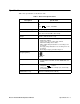
NOTE: Describes additional or critical information. CAUTION: Describes potential damage to equipment. WARNING: ! ~ Describes potential danger that can result in injury or death.
Specifications Table 1 lists specifications for the Beacon 410. Table 1: Beacon 410 Specifications Description Specification Input Power 100/115/220V ~ ±10%, 50/60Hz, 1.0/1.0/0.5A or 24 V ± 10%, 2.5A VDC Construction (housing) Fiberglass/polyester with lexan window (NEMA 4X) Dimensions 12.5 in. H x 11.0 in. W x 6.4 in. D (31.8 cm H x 27.9 cm W x 16.3 cm D) Weight 10.4 lbs. (without AC line cord) Environmental Conditions • • • • • • • For indoor or outdoor locations (Type 4X) 2000m max.
Chapter 2: Description Overview This chapter describes the Beacon 410’s external and internal components. External Description This section describes the housing and all external components of the Beacon 410. For the purposes of this description, the housing door is considered the front of the monitor. Housing The Beacon 410’s fiberglass housing is weather- and corrosion-resistant. It is suitable for installation where general purpose equipment is in use.
Buzzer The buzzer is on the bottom of the housing, behind the reset switch. The buzzer sounds an audible alarm to warn you of gas alarms and instrument failures. Internal Description This section describes the internal components of the Beacon 410.
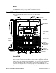
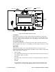
Display Cable Connector Status LEDs LCD Display Control Switches LCD Contrast Adjust Pot Status LEDs Figure 2: Control PCB Component Location LCD Display During normal operation, the four line display simultaneously indicates the target gas, current gas reading, and measuring unit of each active channel. The display also shows messages, settings, and other data when you are operating the various selection menus and operating modes.
wired to the Beacon 410 (see “Chapter 10: Maintenance” on page 64). • Alarm 1 LED The alarm 1 LED is on when the Beacon 410 is experiencing an alarm 1 condition. • ALARM 2 LED The alarm 2 LED is on when the Beacon 410 is experiencing an alarm 2 condition. • ALARM 3 LED The alarm 3 LED is on when the Beacon 410 is experiencing an alarm 3 condition.
CAUTION: The strobe terminals are intended for use with the RKI supplied optional strobe. Consult RKI Instruments, Inc. before attempting to use these terminals for some other alarm device. • Detector/Transmitter Terminal Strips Four detector/transmitter terminal strips are located along the bottom left side of the main PCB (see Figure 1 on page 5). These four 11-point terminal strips facilitate wiring connections to the detector heads.
Table 3: Terminal Assignments for the Controller Terminal Strip (Continued) Terminal Connects to: Alarm Reset Reset Switch Terminals (factory wired) Alarm Reset Alarm Buzzer + Buzzer + connection (factory wired) Alarm Buzzer - Buzzer - connection (factory wired) 1 If 24 VDC is used as primary power source do not make wiring connections to the AC terminal strip. • AC terminal strip The 3-point AC terminal strip is located above the controller terminal strip (see Figure 1 on page 5).
Channel Relays & Fail Relay The eight channel relays are above the channel alarm terminal strip (see Figure 1 on page 5 and Figure 3 on page 9). These relays are dedicated to specific channels. Figure 3 illustrates the allocation of the channel relays. The fail relay is located directly to the left of the channel relays. The fail relay is a common relay. Common/Channel Relays The four common/channel relays are above the common/channel alarm terminal strip (see Figure 1 on page 5 and Figure 3 on page 9).
Optional Accessories This section describes the optional accessories available for the Beacon 410. Both optional accessories are wired to the Strobe Terminal Strip as shown below.
Alarm Strobe The Beacon 410 can be ordered with a red alarm strobe light installed on the top of the housing. The Beacon 410 retains its NEMA 4X rating with the strobe installed. Strobe operation can be programmed in Configuration Mode (see “Chapter 6: Configuration Menu” on page 35). The outline and mounting dimensions with the alarm strobe are the same as the standard Beacon 410 with the excpetion of the height. The difference is shown below. See Figure 7 for all outline and mounting dimensions. .
NOTE: See “Chapter 3: Installation and Start Up” on page 14 for complete Beacon 410 installation instructions. CAUTION: Do not adjust the strobe brightness or the horn volume at the strobe/horn, as this may overload the Beacon 410 strobe control circuit. The horn/strobe does not come factory installed to the Beacon 410. To install the horn/ strobe: 1. Mount the horn/strobe in the desired location. 2.
Chapter 3: Installation and Start Up Overview This chapter describes procedures to mount the Beacon 410 Gas Monitor, make wiring connections to the monitor, and start up the monitor. WARNING: Perform all installation and start-up procedures in a known fresh air environment, an environment free of combustible and toxic gasses and of normal oxygen content. The Beacon 410 is not in operation as a gas monitoring controller until the start up procedure is complete.
10.50 8.00 Ø .31 x .50 slot, 4X 12.94 13.39 12.50 3/4" Conduit Hubs, 4X 6.43 Door Latches 6.25 3.63 Figure 7: Beacon 410 Gas Monitor Outline and Mounting Dimensions Wiring the Beacon 410 Gas Monitor This section describes procedures to connect the AC power source, DC power source, Modbus wiring (refer to “Wiring the Beacon 410 in a Modbus System” on page 54), external alarms, recording devices, and detector heads.
Figure 8: Beacon 410 Gas Monitor External Wiring Diagram 16 • Wiring the Beacon 410 Gas Monitor Beacon 410 Gas Monitor Operator’s Manual W G S R W G B LEL 4-20 mA OUTPUT NO N C C RELAY-B NO NC C RELAY-C RELAY-D NO NC C Alarm Dev ice Power Relay Contacts Rated F or 10 Amps At 250 VAC Alarm Dev ices, Typical Alarm Wiring S hown NO N C C NO N C C NO NC C NO NC C NO N C C NO N C C NO N C C NO N C C CH 1 CH 1 CH 2 CH 2 CH 3 CH 3 CH 4 CH 4 RELAY-1 RELAY-2 RELAY-1 RELAY-2 RELAY-1 RELAY-2 RELAY-1 RE
Connecting the AC Power Source NOTE: If you are using DC power as the primary power source, go to the next section, “Connecting the DC Power Source”. The AC in terminal strip will accept 24 - 14 AWG wire. When selecting wire to connect the AC power source to the Beacon 410, be sure to meet the local electrical code. Also be sure to use an appropriate circuit breaker in the AC line close to the Beacon 410 that meets the local electrical code.
Beacon 410 does not include the battery charging feature, you may use a self contained 24 VDC backup that keeps its’ batteries charged while AC power is on and recharges the batteries when AC power returns after a power failure. If your Beacon 410 includes the battery charging feature, see “Battery Charging (Optional)” on page 25 for a complete description of this feature and what type of battery to use. If DC power is the primary power source, DO NOT connect AC power. 1.
Connecting External Alarms Before connecting any external alarm devices to the relay contacts, make sure you know how you want the devices to operate. For example, confirm under what alarm condition you want a device to turn on or turn off and what channel is going to control the device. Also make sure that the parameter settings that apply to the relays in the Global Menu and the Configuration Menu are set so that the desired alarm device operation is obtained.
Connecting Recorders Perform the following procedure to connect an analog signal recording device to the Beacon 410. The output at the recorder output terminals for each channel is a 4 - 20 mA signal that corresponds to the detection range of the detector head connected to that Beacon 410 channel. Be sure to read the recording device’s operator’s manual before installation and follow all wiring procedures and recommendations made by the recording device’s manufacturer. 1.
detector head to a controller. 4. Install an appropriately rated cable bushing or conduit in an unused conduit hub on the bottom of the Beacon 410 housing. 5. Route the wires in conduit or shielded cable from the detector head through the selected conduit hub into the Beacon 410. See Table 4 below for wire size and distance guidelines. 6. Unshielded twisted pair cable in conduit or shielded twisted pair cable is recommended for all the direct connect detector heads.
page 41 for instructions to setup a new channel. Perform the following procedure to connect a 4 - 20 mA transmitter which you supply to the Beacon 410. 1. Turn off or unplug power to the Beacon 410. 2. Open the Beacon 410 door and turn off the power switch. CAUTION: The power switch does not control DC input power. 3. See the transmitter’s operator’s manual for instructions on how to connect wires to the transmitter. 4.
4. Plug in or turn on the incoming power source (AC or DC). 5. Turn on the power switch if AC power is used as primary power. 6. The following screen appears for a few seconds. R K I I n s t r u m e n t s B e a c o n 4 1 0 7. The Version Screen then appears. It shows the instrument’s hardware and firmware versions for a few seconds. HW is the hardware version. Main is the main firmware version. MB is the Modbus firmware version.
Chapter 4: Operation Overview This chapter describes the Beacon 410 Gas Monitor in normal operation. This chapter also describes the Beacon 410 in alarm 1, alarm 2, alarm 3, and fail conditions, and suggests responses to these conditions. Normal Operation Normal operation is defined as follows: • the start-up procedure is complete. • the Beacon 410 is not indicating an alarm 1, alarm 2, alarm 3, or fail condition. • the Beacon 410 is not running in one of the selection menus or Calibration Mode.
• If you enter the Global Menu, the Configuration Menu, the Input Setup Menu, the Modbus Menu, or Calibration Mode, the signal output will be fixed at 3.5 mA until the Beacon 410 returns to normal operation. • If the Beacon 410’s input power decreases below 18.5 volts so that the Beacon 410 is in a low power alarm, the signal output is fixed at 0.7 mA until the low power alarm is cleared. • If the Beacon 410 goes into a fail condition, after a 30 second delay, the signal output is fixed at 0.
The battery charging circuit is designed to charge lead acid type batteries. If AC power is used as primary power and a backup battery is connected to the Beacon 410 ‘s EXT DC/ 24V BATT terminals as shown in Figure 10 on page 18, the battery charging feature will charge the battery if it is depleted and keep it charged with a charge current of approximately 100 mA.
Table 5: Visual and Audible Alarm Indications Condition Cause Alarm 3 Increasing (decreasing for O2) gas reading at or above (below for O2) the alarm 3 setpoint Visual Indication(s) • • • • Fail • • Disconnected or misconnected detector head wiring Display reading below -10% of full scale or lower Malfunctioning components • • • Audible Indication Alarm 1, alarm 2, and alarm 3 LEDs (alarm 1 and alarm 3 for oxygen) are on Gas reading alternates with ALM 1,2,3 (ALM 1,3 for oxygen) message If instal
NOTE: Relay D is factory set as a common any alarm relay. • the applicable alarm 1 channel relay energizes • if installed and set to activate in an alarm 1 condition, the strobe flashes Responding to an Alarm 1 Condition This section suggests the following responses to an alarm 1 condition: 1. Follow your established procedure for a low-level combustible or toxic gas condition or a decreasing oxygen condition. 2.
or an increasing oxygen condition. 2. To acknowledge the alarm condition and silence the buzzer while in an alarm 2 condition, press and release the reset switch. The alarm 2 LED will begin to flash indicating the alarm condition has been acknowledged. You cannot de-energize the alarm 2 relays until the gas reading falls below the alarm 2 setpoint. 3. Oxygen alarms are factory set as self-resetting and will automatically clear when the oxygen reading falls below the alarm 2 setpoint. 4.
common alarm 3 relay (relay C) until the gas reading falls below the alarm 3 setpoint. 3. Oxygen alarms are factory set as self-resetting and will automatically clear when the oxygen reading rises above the alarm 3 setpoint. 4. Alarms for all other gas types are factory set as latching. After the gas reading falls below the alarm 3 setpoint, press and release the reset switch to reset the alarm circuit.
WARNING: While in a low power condition, the Beacon 410 is not an active gas monitor. When the Beacon 410 senses a low DC power condition, it alerts you as follows: • The FAIL LED turns on. • The fail relay and all other relays are de-energized. • The message LOW POWER S STANDBY is indicated on the top line of the LCD and the input voltage is displayed on the bottom line of the LCD. NOTE: The low DC power alarm cannot be cleared using the reset switch. When the DC input voltage increases to 19.
Chapter 5: Global Menu Overview This chapter describes how to view and change Beacon 410 instrument parameters using the Global Menu. The global parameters are the optional strobe’s installation setting, the relay normal state setting, the usage setting for relays A, B, C, and D, and the buzzer silence setting. The Global Menu is accessed using the ESCAPE and UP/YES control buttons. The Global Menu includes a 5-minute timeout feature.
3. In the parameter screens, use the ENTER button to accept a displayed parameter setting and proceed to the next parameter or the ESCAPE button to backup a screen. 4. If you want to change a displayed parameter setting, use the UP/YES or DOWN/NO button to change the parameter to the desired setting, then press and release the ENTER button to accept the change and proceed to the next screen. 5.
Table 6: Global Menu Parameters (Continued) Global Parameter (Factory-Set Value) NORMAL RELAY STATES (NORM DE-ENERGIZED) Description If set to NORM DE-ENERGIZED, the gas alarm relays are de-energized in normal operation and energize when the appropriate alarm circuit is activated. The NO (normally open) relay contacts are open during non-alarm operation and close when the appropriate alarm condition occurs.
Chapter 6: Configuration Menu Overview This chapter describes how to view and change Beacon 410 channel parameters including alarm point settings and channel relay settings using the Configuration Menu. The Configuration Menu is accessed using the ESCAPE and ENTER control buttons. The Configuration Menu includes a 5-minute timeout feature. If you do not press a control button for 5 minutes, the Beacon 410 automatically returns to normal operation.
4. Press and release the UP /YES or DOWN/NO button until the setting you want to select appears, then press and release the ENTER button to save it. The next channel parameter screen appears. NOTE: If you selected STANDBY or NOT USED, the display will ask you if you still want to review the channel settings. If yes, press and release the UP/YES button and continue with step 5. If no, press and release the DOWN/NO button and proceed to step 9. NOTE: Use the ESCAPE button to go backwards in the menu. 5.
Table 7 below lists the channel parameters that can be viewed and updated in the Configuration Menu along with the factory set value for each parameter. Table 7: Configuration Menu Parameters Channel Parameter (Factory-Set Value) Description Channel Status (Factory setting depends on whether a detector is supplied for a channel.) If set to ACTIVE, the channel will be fully functional. If set to STANDBY, the channel’s gas name and reading will be replaced by STANDBY on the display.
Table 7: Configuration Menu Parameters (Continued) Channel Parameter (Factory-Set Value) ALM-1 STROBE Setting (NonResettable STROBE) Description If set to Resettable STROBE, the strobe can be turned off with the Reset Switch while an alarm 1 condition still exists. If set to NonResettable STROBE, the strobe cannot be turned off with the Reset Switch while an alarm 1 condition still exists. If set to NO STROBE, the strobe will not activate due to an alarm 1 condition.
Table 7: Configuration Menu Parameters (Continued) Channel Parameter (Factory-Set Value) Description Alarm-3 Level (See the Beacon 410 Detector Head Specification sheet for the detector head installed on this channel.) The gas reading at which an alarm 3 condition occurs and the Beacon 410 activates the alarm 3 circuit for this channel.
Table 7: Configuration Menu Parameters (Continued) Channel Parameter (Factory-Set Value) Relay-2 Assignment (ALARM-2) Description The alarm condition that activates relay 2. It can be set for activation by the following alarm conditions: • • • • • • • • ALARM-1 ALARM-2 ALARM-3 ALARMS 1 or 2 ALARMS 1 or 3 ALARMS 2 or 3 ALARMS 1, 2, or 3 Use As Channel FAIL (If you choose this setting, the relay is normally energized) Relay-X Assignment (ALARM-3) The alarm condition that activates relay X.
Chapter 7: Input Setup Menu Overview This chapter describes how to use the Input Setup Menu to select each channel’s detector head input type and the gas setup. The detector head input type determines whether a direct connect type or a 4 - 20 mA type of detector head will be used and the gas setup determines the target gas, detection units, and the detection range full scale. The Input Setup Menu is accessed using the ENTER control button when powering up the Beacon 410.
4. The setup that you perform will apply to all the channels that you select. Select the channel or channels you want to setup by using the UP/YES or DOWN/NO buttons to scroll through the choices and then press and release the ENTER button to accept the selection. The INPUT Type screen will appear. In the example below, channels 1 and 2 have been selected for setup. C H A I N P 4 U P / N U 2 D N E L ( T T y 0 m A N t h S p T e ) : 1 , 2 e R A N S M I T T E R n E N T / E S C 5.
7. Use UP/YES or DOWN/NO button to scroll through the gas setup choices. There are several choices whose gas name, full scale, and detection units are predefined. For these choices, the gas name, full scale, and detection units are displayed. There is also one choice named CUSTOM that allows you to enter the gas name, full scale, and detection units. 8. When the desired setup choice is shown on the display, press and release the ENTER button to accept it.
10. If you want to save the setup, press and release the UP/YES button. The display will indicate that the settings have been saved before asking if you want to setup more channels. NOTE: If you defined a custom setup by selecting the CUSTOM choice in the PreDefined Gas Setup screen, you will be required to review the channel parameters from the Configuration Menu. See “Viewing and Changing Channel Parameters” on page 35 for a description of the channel parameters.
Chapter 8: Calibration Mode Overview This chapter describes how to calibrate the Beacon 410’s active channels using Calibration Mode. In Calibration Mode, you can: • Set the calibration timeout. • Perform a fresh air adjust on selected channels. • Perform a gas adjust on selected channels. • View Max Spans. Table 9 below briefly describes the four operations that can be performed in Calibration Mode. A more detailed description of each operation is given later in this chapter.
detection using catalytic combustion type detectors, if potential catalyst poisons are known or likely to be present, more frequent calibration than every 3 months will be necessary. Detector Head Types The Beacon 410 can support both direct connect (internal amp) and 4-20 mA transmitter (remote amp) detector heads. Since the Beacon 410 can support both types of detector heads, there are three possible detector head combinations when calibrating the active channels: • Direct connect detector heads only.
Entering Calibration Mode WARNING: The Beacon 410 is not an active gas monitoring device during the calibration procedure. When you enter Calibration Mode, the 4-20 mA output signal will “freeze” at 3.5 mA for each active channel, all relays and alarm LEDs will remain in their current state at the time that you entered Calibration Mode, and the alarm buzzer and strobe will turn off if they were activated until you exit Calibration Mode.
2. With SET CAL TIMEOUT displayed, press and release the ENTER button. The Calibration Timeout Screen appears. C a l i b r a t i o n U P / D N T i m e o u t 1 5 m i n u t e s t h e n E N T / E S C 3. Use the UP/YES or DOWN/NO button to adjust the calibration timeout to the desired setting. The calibration timeout can be set from 5 minutes to 240 minutes (4 hours) in 5 minute increments. The factory set calibration timeout is 15 minutes. 4.
4. Use the UP/YES or DOWN/NO button to scroll through the channel combination choices and select the channel or channels that you will air adjust. 5. Press and release the ENTER button to accept the displayed choice and continue with the air adjustment. The display will alternate between the top two screens shown below. In the example below, channels 1, 2, 3, and 4 have been selected.for an air adjust.
not successful for any channel, the display will indicate AIR ADJUST FAILED for that channel. The Beacon 410 will then return to the Select Operation screen. If you suspect the detector area is not a fresh air environment, apply zero air to each selected detector before pressing the ENTER button to perform the fresh air adjustment. See each detector head’s operator’s manual for instructions to apply zero air to each detector.
6. Use the UP/YES and DOWN;/NO buttons to make the displayed concentration match the calibration gas concentration, then press and release the ENTER button to accept it. The display will show the expected calibration gas concentration for the next selected direct connect type channel. 7. Repeat step 6 for each selected direct connect channel. When the last selected direct connect channel’s calibration gas concentration has been accepted, the top two screens shown below will alternate.
11. After you have applied gas to each direct connect detector head, press and release the ENTER button. The Beacon 410 will perform a gas adjustment on the direct connect type channels and indicate GAS ADJUST PASSED for each direct connect type channel. If the air adjust was not successful for any channel, the display will indicate AIR ADJUST FAILED for that channel. The Beacon 410 will then return to the Select Operation screen. 12.
3. Press and hold the ENTER button to display the maximum spans. In the example below, channels 1, 2, and 3 are active and channel 2 is a 4 - 20 mA type channel. 1 : 2 : 3 : M E T H A N E 1 5 0 + % L E L 4 - 2 0 mA Xm t r O X Y G E N 3 7 . 5 % :V O L 4. Release the ENTER button to return to the Select Operation screen. 5. Press and release the ESCAPE button to return to the initial Calibration Mode Screen that says You Have Entered the CALIBRATION Menu...
Chapter 9: RS-485 Modbus Output Overview This chapter describes the Beacon 410’s RS-485 Modbus output and how to configure the Beacon 410 to make use of it. It also discusses how to wire the Beacon 410 into a Modbus system. The Beacon 410 provides an RS-485 serial communications interface. It is a Modbus Slave Device, supporting 2-wire RS-485 Modbus RTU serial communications. Wiring the Beacon 410 in a Modbus System The Beacon 410 is a 2-wire Modbus RTU device.
Recommended Modbus Wiring The recommended Modbus wiring for the Beacon 410 is illustrated in Figure 14 below.
ID = 32 ID = 1 Modbus Master Beacon 410 Termination Jumper Installed Beacon 410 Termination Jumper Installed RS-485 RS-485 Beacon 410 Beacon 410 Beacon 410 Beacon 410 Termination Jumper Not Installed Termination Jumper Not Installed Termination Jumper Not Installed Termination Jumper Not Installed ID = 2 ID = 3 ID = 4 ID = 31 Up to 32 Beacon 410s can be connected without a repeater.
2. Press and release the UP/YES button to continue in the Modbus Menu to the Modbus Feature Enable/Disable screen. MO D B U S U P / D N 3. F e a t u r e i s : D I S A B L E D t h e n E N T / E S C In the parameter screens, use the ENTER button to accept a displayed parameter setting and proceed to the next parameter or the ESCAPE button to backup a screen. 4.
Table 11: Modbus Configuration Parameters (Continued) Modbus Mode Parameter Response Delay Available Settings & Description The response delay can be set from 0 (factory setting) to 20 mS. This is an optional additional delay inserted by the Beacon 410 prior to returning a response message to the Master. It may be helpful in some installations where the Master’s preparedness to receive responses might be delayed.
Registers 40002 - 40015, Channel 1 Information Register 40002 Table 13 below shows the information in register 40002.
ASCII characters. Registers 40016 - 40029, Channel 2 Information Register 40016 Table 15 below shows the information in register 40016.
Registers 40028 - 40029 The 4 bytes (characters) in registers 40028 and 40029 represent the channel gas units in ASCII characters. Registers 40030 - 40043, Channel 3 Information Register 40030 Table 17 below shows the information in register 40030.
characters. Registers 40042 - 40043 The 4 bytes (characters) in registers 40042 and 40043 contain the channel gas units in ASCII characters. Registers 40044 - 40057, Channel 4 Information Register 40044 Table 19 below shows the information in register 40044.
Registers 40053 - 40055 The 6 bytes (characters) in these registers contain the channel gas reading in ASCII characters. Registers 40056 - 40057 The 4 bytes (characters) in registers 40056 and 40057 contain the channel gas units in ASCII characters.
Chapter 10: Maintenance Overview This chapter describes preventive maintenance procedures for the Beacon 410 and how to replace the AC fuses. It includes a troubleshooting guide for problems you may encounter with the Beacon 410. Preventive Maintenance Preventive maintenance of the Beacon 410 consists of daily, monthly, and quarterly procedures to ensure that the installed detector heads remain on zero (20.9 for oxygen) in fresh air and are responsive to the target gas.
Table 21: Troubleshooting the Beacon 410 (Continued) Condition Frequent or Suspect Alarms Symptom(s) • • Momentarily Unstable Gas Readings on Display • Probable Causes The Beacon 410 alerts you to frequent or suspect alarms. The detector heads’ fresh air readings remain on zero (20.9 for oxygen) despite alarm occurrences. • The display reading for one or more channels rises or falls briefly and then returns to the normal fresh air reading.
Replacing the AC Fuses The Beacon 410 has two user serviceable AC fuses. NOTE: To replace other components of the Beacon 410, contact RKI Instruments, Inc., for further information. 1. Turn off or unplug all incoming power to the Beacon 410. 2. Open the Beacon 410 housing door, then place the power switch in the OFF position. 3. The fuses are located to the left of the AC in terminal strip. Use a flat-blade screwdriver to rotate the applicable fuse holder 1/4 turn counterclockwise.