GasWatch 2 Operator’s Manual Part Number: 71-0065RK Revision: F Released: 2/2/11 www.rkiinstruments.
WARNING Read and understand this instruction manual before operating instrument. Improper use of the gas monitor could result in bodily harm or death. Periodic calibration and maintenance of the gas monitor is essential for proper operation and correct readings. Please calibrate and maintain this instrument regularly! Frequency of calibration depends upon the type of use you have and the sensor types.
Warranty RKI Instruments, Inc. warrants the GasWatch 2 sold by us to be free from defects in materials, workmanship, and performance for a period of two years from the date of shipment from RKI Instruments, Inc. This includes the instrument and the original sensors. Replacement parts are warranted for 1 year from the date of their shipment from RKI Instruments, Inc. Any parts found defective within their warranty period will be repaired or replaced, at our option, free of charge.
Table of Contents Introduction . . . . . . . . . . . . . . . . . . . . . . . . . . . . . . . . . . . . . . . . . . . . . . . . . . . . . . . . . . 1 Specifications. . . . . . . . . . . . . . . . . . . . . . . . . . . . . . . . . . . . . . . . . . . . . . . . . . . . . . . . . 2 Description . . . . . . . . . . . . . . . . . . . . . . . . . . . . . . . . . . . . . . . . . . . . . . . . . . . . . . . . . . . 4 Case . . . . . . . . . . . . . . . . . . . . . . . . . . . . . . . . . . . . . . . . . . . . . . . .
Maintenance . . . . . . . . . . . . . . . . . . . . . . . . . . . . . . . . . . . . . . . . . . . . . . . . . . . . . . . . . 24 Troubleshooting . . . . . . . . . . . . . . . . . . . . . . . . . . . . . . . . . . . . . . . . . . . . . . . . . 24 Replacing the Lithium Battery . . . . . . . . . . . . . . . . . . . . . . . . . . . . . . . . . . . . . . . 25 Replacing the Sensor . . . . . . . . . . . . . . . . . . . . . . . . . . . . . . . . . . . . . . . . . . . . . 27 Replacing the Sensor Cover . . . . . . .
Introduction Using an advanced microprocessor controlled detection system, the GasWatch 2 Personal Single-Gas Monitor detects the presence of either carbon monoxide (CO), hydrogen sulfide (H2S), or oxygen (O2). The GasWatch 2’s compact size and easy-to-use design makes it ideally suited for a wide range of applications, including sewage treatment plants, tunnels, hazardous waste sites, petrochemical facilities, oil fields, mines, and chemical plants.
Specifications Table 1: GasWatch 2 Specifications GW-2C GW-2H GW-2X Target Gas Carbon Monoxide (CO) Hydrogen Sulfide (H2S) Oxygen (O2) Detection Range 0 to 500 ppm 0 to 100.0 ppm 0 to 40.0% vol. Display Increment 1 ppm 0.5 ppm 0.1% vol. Detection Principle Electro Chemical Electro Chemical Galvanic Cell Alarm Points Low High TWA STEL 25 ppm 50 ppm 25 ppm 200 ppm Low High TWA STEL 10.0 ppm 30.0 ppm 10.0 ppm 15.0 ppm Low 19.5% vol. (decreasing) High 23.5% vol.
Table 1: GasWatch 2 Specifications GW-2C Optional Accessories GW-2H GW-2X • Belt Clip • Hard Hat Clip • Lapel Clip Dimensions and Weight Dimensions: 2.5 (H), 1.7 (W), 0.9 (D) inches Weight: 2 oz. Operating Temp.
Description This section describes the components of the GasWatch 2. These components include the GasWatch 2’s case, wristband, sensor cap and sensor cover, charcoal filter disk (in the GW-2C), sensor, LCD, control buttons, printed circuit boards, alarm lights, buzzer, vibrator, and lithium battery.
Case The GasWatch 2’s sturdy, high-impact plastic case is suitable for use in many environmental conditions, indoors and out. The unit is dust proof and weather resistant. The case has two halves, the top case and the bottom case. They are held together by four screws in the bottom case. The case is a different color depending on the model. The GW-2C for CO is red, the GW-2H for H2S is orange, and the GW-2X for oxygen is blue. The digital LCD is visible through the top case.
Sensor The GasWatch 2 uses either an oxygen, CO, or H2S sensor. The sensor is protected by the white sensor cover which is held in place by the sensor cap and sensor gasket. The sensor cover allows ambient air to diffuse past it to the sensor. The three sensors used in the three GasWatch 2 models use different detection principles as described below. Oxygen Sensor The oxygen sensor is a galvanic type of sensor.
Table 2: The Control Buttons of the GasWatch 2 Button Function POWER/MODE • Turns the unit on and off. • Turns the LCD back light on. • Displays STEL and TWA readings (GW-2H & GW2C). • Displays peak readings (high for GW-2H & GW-2C and low & high for GW-2X). • Resets the alarm circuit (gas alarms). • Enters Calibration Mode with the AIR button. • Enters Alarm Adjustment Mode with the AIR button. • Enters Time Adjustment Mode with the AIR button. AIR • Turns the LCD back light on.
Alarm Lights The GasWatch 2 has two alarm lights located above the LCD. The alarm lights are two red LEDs that alert you to gas, low battery, and sensor failure alarms. They are visible through a frosted lens. Buzzer A solid-state electronic buzzer is mounted inside the GasWatch 2. An opening on the left side of the top case allows the buzzer’s sound to resonate from the case.
Start Up This section explains how to start up the GasWatch 2 and to get it ready for operation. Start-up Procedure 1. Press and hold the POWER/MODE button for one second to turn on the GasWatch 2. The the buzzer sounds briefly, the vibrator vibrates briefly, all elements of display are activated, and the alarm lights and LCD backlight turn on for a few seconds. 2. The GasWatch 2 then displays the target gas and time before displaying the battery voltage.
3. When the fresh air readings have been set, the LCD displays “Adj” for 2 seconds which prompts you to release the AIR button. The unit will set the reading to 0 ppm for the GW-2C and GW-2H and to 20.9% oxygen for the GW-2X. 4. The unit then returns to normal operation and the display indicates the current gas concentration. Turning Off the GasWatch 2 1. Press and hold the POWER/MODE button for about five seconds to turn off the unit.
Operation This section describes the normal operation of the GasWatch 2. It explains how the unit can be used to display peak, STEL, and TWA readings for the GW-2C and GW-2C, and minimum and maximum readings for the GW-2X. It also covers alarm indications. Measuring Mode After you have powered up the GasWatch 2 and performed a fresh air adjustment following the instructions of the previous section, “Start Up”, the GasWatch 2 is in Measuring Mode.
1. Make sure the GasWatch 2 is in Measuring Mode. The current gas concentration should be displayed on the LCD. 2. Press and release the POWER/MODE button to enter Peak Display Mode. This will activate the LCD backlight and display the Peak reading. A small Peak symbol is displayed in the upper left corner of the LCD. 3. Press and release the POWER/MODE button again to enter STEL Display Mode. This will display the STEL reading. The word “STEL” is displayed in the middle of the LCD above the reading. 4.
Alarms This section covers alarm indications. It also tells you how to reset the GasWatch 2 after an alarm has occurred and how to respond to an alarm condition. Alarm Indications, GW-2C & GW-2H The GW-2C and the GW-2H will sound an alarm and the unit will vibrate when the target gas concentration, CO or H2S, rises above the low alarm point. The GasWatch 2 also sounds an alarm and vibrates when the high alarm point, the STEL alarm point, or the TWA alarm point is reached.
Table 3: Alarm Types and Indications Alarm Type TWA or STEL (GW-2C & GW-2H Only) Concentration of CO or H2S rises above the TWA or STEL alarm point. Over Range LCD Indications Other Indications • Back light turns on. • TWA or STEL blinks to the left of the battery icon. • If the unit is in both TWA alarm and STEL alarm, both TWA and STEL will be displayed. • Pulsing tone once per second. • Unit vibrates once per second. • Alarm light flashes once per second.
Resetting Gas Alarms To reset a gas alarm, press the POWER/MODE button after the gas reading falls below the low alarm point (or above for the GW-2X). If a TWA or STEL alarm has been activated, it cannot be reset unless you turn off the unit. NOTE: Even though the gas concentration may have returned to normal or may have fallen below the alarm point, the alarm indications will continue until you have reset the alarm using the MODE/POWER button.
Responding to Battery Alarms WARNING: The GasWatch 2 is not operational as a gas monitoring device during a dead battery alarm. Take the GasWatch 2 to a non-hazardous area and change the battery as described in “Changing the Lithium Battery”. The GasWatch 2 is fully functional in a low battery warning condition. However, only a couple of days of operation may remain depending on certain conditions such as alarm occurrences.
Displaying and Setting the Alarm Points The GasWatch 2 allows you to display and set the alarm points. There is a Low Alarm point and a High alarm point on all three models. The GW-2C and GW-2H also have STEL and TWA alarm points. The alarm points and their factory settings for the three GasWatch 2 models are summarized in the table below: Table 4: Alarm Points of the Four Target Gasses Model Low Alarm High Alarm STEL TWA GW-2C (CO) 25 ppm 50 ppm 200 ppm 25 ppm GW-2H (H2S) 10.0 ppm 30.0 ppm 15.
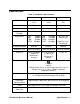
3. As soon as segments appear on the display (approximately one second), release the AIR button. When the unit “beeps,” release the POWER/MODE button to put the GasWatch 2 into Alarm Point Adjustment Mode. The LCD should display the Low Alarm setting for the target gas and the battery level. . Rising Alarm Battery level 10.0 Alarm point ppm Alarm LO Name Figure 3: LCD in Alarm Adjustment Mode, GW-2C & GW-2H Falling Alarm Alarm Name Battery level . 19.
NOTE: You can only cycle through the alarm points once before the GasWatch 2 goes into its startup sequence followed by Measuring Mode. If you want to cycle through the alarm points again, press and hold the POWER/MODE button to turn off the GasWatch 2. Then begin with step 2 above to put the unit back into Alarm Point Adjustment Mode. 6. When you are finished viewing or adjusting the alarm point settings, press and release the POWER button repeatedly until the ROM number for your unit appears on the LCD.
Setting the Time The GasWatch 2 allows you to set the time. 1. Make sure the GasWatch 2 is on and in Measuring Mode. 2. Press and hold the Air button, then press and hold the POWER/MODE button to put the GasWatch 2 into Time Adjustment Mode. Release the buttons when the word “SEt” appears on the LCD. Below “SEt”, the time will be displayed and the hour in the time will be flashing. Battery level Hour SEt 21:19 Minute Figure 5: LCD in Time Adjustment Mode 3.
Calibration This section covers the calibration of the GasWatch 2. Setting the fresh air reading is described first followed by setting the span (GW-2C and GW-2H) and zero (GW-2X) reading. You are told what is needed to complete the task, how to assemble the calibration kit, and how to set the span (zero for GW-2X) reading. WARNING: Use a 0.5 LPM (liters per minute) fixed flow regulator when calibrating. Use of a different flow rate may adversely affect the accuracy of the calibration.
NOTE: On the GW-2X, instead of 100% nitrogen (0% oxygen), it is allowable to use an oxygen concentration of up to 19.5% to set the zero reading. • To carry out the calibration, you will need a fixed-flow regulator with an on/off knob and a flow rate of 0.5 LPM (liters per minute), nonabsorbent tubing, and the calibration adapter that will fit over the GasWatch 2’s sensor. Assembling the Calibration Kit WARNING: Calibrate the GasWatch 2 in a non-hazardous environment. 1.
8. Let the gas flow for one minute and then press the POWER/MODE button. The unit will adjust the span (GW-2C or GW-2H) or zero (GW2X) based on the calibration value that was saved in step 5 above. 9. Turn the regulator knob clockwise to close the regulator. 10. Remove the regulator from the gas cylinder and the calibration adapter from the unit. As soon as the unit makes the calibration adjustment, it will begin its startup sequence and then enter Measuring Mode.
Maintenance This section describes troubleshooting procedures for the GasWatch 2. It also describes how to change the GasWatch 2’s battery as well as how to replace the sensor cover and gas sensor. WARNING: RKI Instruments, Inc. recommends that service, calibration, and repair of RKI instruments be performed by personnel properly trained for this work. Replacing sensors and other parts with original equipment does not affect the intrinsic safety of the instrument.
Table 5: Troubleshooting the GasWatch 2 Symptoms Probable Causes Recommended Action • “FAIL” displays during span or zero adjustment. • The calibration value may not match the cylinder gas concentration. • The sample gas is not reaching the sensor because of a bad connection. • The calibration cylinder may be out of gas or is outdated. • The sensor may need replacement. 1. Check all calibration tubing for leaks or for any bad connections. 2.
1. Verify that the GasWatch 2 is off. 2. On the back of the unit, unscrew the two screws that retain the battery cover far enough so you can pull the cover away from the bottom case. The screws are held captive in the battery cover if you do not unscrew them too far. Battery Cover Lithium Battery, CR 2450 + Note: Shown w/out wristband. Figure 6: Changing the Battery 3. Carefully remove the old battery. 4.
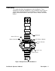
9. Press the POWER/MODE button to accept the hour setting. The minute starts flashing. 10. Use the Air button to increase the minute setting to the desired setting. 11. Press the POWER/MODE button to accept the minute setting. The unit will begin its startup sequence and the enter Measuring Mode. Replacing the Sensor WARNING: Replace the sensor in a non-hazardous environment. 1. Verify that the GasWatch 2 is off. 2. With a flat blade screw driver, gently pry off the sensor cap.
Tab Align slots in CO and H2S sensor with tabs in case. RKI POWER MODE AIR Tab Note: Oxygen sensor is not keyed. Unit shown w/out wristband. Figure 8: Replacing the Sensor 5. Carefully insert the replacement sensor in the socket. Make sure the sensor face with the colored ring is facing up. CAUTION: When replacing the sensor, verify that the sensor is properly aligned with its socket before inserting it into the socket.
Replacing the Charcoal Filter Disk WARNING: Replace the charcoal filter disk in a non-hazardous environment. 1. Verify that the GasWatch 2 is off. 2. With a flat blade screw driver, gently pry off the sensor cap. It snaps onto the top case with two tabs. 3. Remove the old charcoal filter from its recess in the sensor gasket. 4. Install the new charcoal filter into its recess in the sensor gasket. 5. Replace the sensor cover into its recess in the sensor gasket. 6. Reinstall the sensor cap.
Wristband Use spring bar tool to remove spring bars. POWER MODE AIR Figure 9: Removing the Spring Bars 2. Remove the spring bars from the old wristband. The spring bar is protected by a hollow sleeve that is inserted in the wristband. The hollow sleeve may remain inside the old wrist band when the spring bar comes out. Be sure to remove the outer sleeve from the wrist band. 3. Insert the hollow sleeves and spring bars into the new wristband. 4.
Parts List Table 6 lists replacement parts and accessories for the GasWatch 2.
Table 6: Parts List Part Number Description 81-GW2H-LV Calibration kit for GW-2H, one 34 liter aluminum gas cylinder (25 ppm H2S in nitrogen), regulator, calibration cup, case, & tubing 81-GW2X-LV Calibration kit for GW-2Xone 34 liter steel gas cylinder (100% nitrogen), regulator, calibration cup, case, tubing 82-0001RK Spring bar tool ES-1821 Carbon monoxide sensor ES-1821L Carbon monoxide sensor, for low humidity use ES-1827 Hydrogen sulfide sensor ES-1827L Hydrogen sulfide sensor, for low