RI-215A Operator’s Manual Part Number: 71-0045RK Revision 0 Released: 10/3/05
Warranty RKI Instruments, Inc., warrants gas alarm equipment sold by us to be free from defects in materials and workmanship, and performance for a period of one year from date of shipment from RKI Instruments, Inc. Any parts found defective within that period will be repaired or replaced, at our option, free of charge.
Table of Contents Chapter 1: Introduction . . . . . . . . . . . . . . . . . . . . . . . . . . . . . . . . . . . . . . . . . . . . . . . . . 5 Overview. . . . . . . . . . . . . . . . . . . . . . . . . . . . . . . . . . . . . . . . . . . . . . . . . . . . . . . . . . . . . . . . . . . . . About the RI-215A . . . . . . . . . . . . . . . . . . . . . . . . . . . . . . . . . . . . . . . . . . . . . . . . . . . . . . . . . . . . . Measuring Mode . . . . . . . . . . . . . . . . . . . . . . . . . . . . . . . . . . .
Verifying the Alarm Point . . . . . . . . . . . . . . . . . . . . . . . . . . . . . . . . . . . . . . . . . . . . . . . . . 18 Adjusting the Alarm Point . . . . . . . . . . . . . . . . . . . . . . . . . . . . . . . . . . . . . . . . . . . . . . . . 18 Chapter 5: Maintenance . . . . . . . . . . . . . . . . . . . . . . . . . . . . . . . . . . . . . . . . . . . . . . . 20 Overview. . . . . . . . . . . . . . . . . . . . . . . . . . . . . . . . . . . . . . . . . . . . . . . . . . . . . . . . . . . . . . . . . .
Chapter 1: Introduction Overview This chapter briefly describes the RI-215A. This chapter also describes the RI-215A Operator’s Manual (this document). Table 1 at the end of this chapter lists the specifications for the RI-215A. About the RI-215A The RI-215A Air Quality Monitor detects the presence of CO2 (carbon dioxide) using an infrared (IR) gas sensor. The RI-215A shows increasing levels of CO2 on its liquid crystal display (LCD).
Specifications Table 1 lists specifications for the RI-215A. Table 1: Specifications Power Source 24 VAC or 24 VDC Target Gas CO2 (carbon dioxide) Sampling Method Diffusion Area Classification Indoor, nonhazardous locations Signal Output 4 to 20 mA Accuracy ± 5% of full scale Fuse1 0. 5A, 125 V (5 mm x 20 mm) 1 A 0.5A, 250 V fuse is an acceptable replacement. About this Manual The RI-215A Operator’s Manual uses the following conventions for notes, cautions, and warnings.
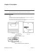
Chapter 2: Description Overview This section describes the external and internal components of the RI-215A. External Description Case The RI-215A’s steel case is radio frequency (RF)-resistant. It is suitable for installation in indoor areas where general purpose equipment is in use. The case has a front housing and a base plate, which snap together. The front housing has a LCD window, which is shown in the front view of Figure 1.
On the bottom of the front housing is a series of slots and a calibration port. The slots allow the target gas sample to enter the IR gas sensor in the RI-215A. The calibration port is covered with a rubber cap. The calibration port accepts 1/4 -inch ID (inside diameter) flexible tubing. A series of switches are accessible to the right of the calibration port, as shown in Figure 1 on page 7.
LCD The LCD is mounted to the printed circuit board. The LCD shows the current gas reading of the RI-215A’s target gas. The LCD also shows operational messages when the RI-215A exceeds its full scale. IR Gas Detector The IR detector uses infrared light and an infrared sensor to detect CO2. A small infrared light source is located in the detector. As CO2 enters the detector, it absorbs infrared light in a characteristic way as the concentration increases.
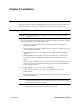
Chapter 3: Installation Overview This chapter describes how to install the RI-215A at the monitoring site. This section also includes procedures to make power and other wiring connections to the RI-215A. Mounting the RI-215A CAUTION: The RI-215A is suitable for installation in indoor areas where general purpose equipment is in use. 1. 2. Select a mounting site that is representative of the monitoring environment.
3. Use two screws to secure the base plate to the wall. Figure 2 below shows the location of the screw holes in the base plate. 1.23 3.08 3.08 Front View Right Side View 2.37 .25 .17 Diameter Mounting Hole Location Back Side Figure 2: RI-215A Outline and Mounting Dimensions 4. Reassemble the base plate and the front housing of the RI-215A in the reverse order as described in step 2 above.
Wiring the RI-215A This section describes procedures to connect power to the RI-215A. This section also describes optional procedures to connect a controller or recorder and external alarm device to the RI-215A. WARNING: To reduce the risk of electric shock, always verify that power to the RI215A has been turned off before making any wiring connections to the RI215A.
Figure 4 below shows how to wire the RI-215A to a controller that accepts 3-wire, 4-20 mA transmitters. RI-215A Controller Terminals 1 (red) + 24 VDC 2 (red) - (DC Ground) 4 - 20 mA In (S or FB) 3 (white) 4 (white) Normally Open Relay Contact 5 (yellow) 6 (blue) Not Used Figure 4: Wiring Diagram of the RI-215A as a 3-Wire 4-20 mA Transmitter Connecting Power 1. Verify that power to the RI-215A has been turned OFF. 2. Connect the two red AC line cables to the 24 VAC or 24 VDC power source.
Connecting the RI-215A to a Controller Perform the following procedure to connect the RI-215A as a 3-wire 4 - 20 mA transmitter to a controller. 1. Verify that power to the RI-215A has been turned OFF. 2. Connect one of the red wires from the RI-215A to the +24V transmitter terminal at the controller. 3. Connect the other red wire to the - (DC ground) transmitter terminal at the controller. 4. Connect the yellow wire to the S or FB transmitter terminal at the controller.
Preparing to Set the Zero Connect the sample tubing from your calibration kit to the hose barb on the fixed flow regulator. The fixed flow regulator should be a 0.5 LPM regulator. NOTE: Do not connect the regulator to the calibration cylinder at this time. Setting the Zero Reading 1. Locate the function switches on the bottom of the unit. 2. Press and hold the MODE switch (M) for three seconds to enter Maintenance Mode. The display will show “1” to indicate Zero Adjustment Mode. 3.
Chapter 4: Operation Overview This chapter describes Measuring Mode and Alarm Adjust Mode. Under Measuring Mode, alarm indications are discussed along with responding to alarms, analog output, and alarm point and ventilation control. Under Alarm Adjust Mode, verifying the alarm point and adjusting the alarm point are described.
Analog Output The RI-215A’s analog output, available via the yellow and blue wires of the cable assembly (refer to Figure 3 on page 12), is proportional to the concentration of CO2 for all gas ranges (e.g., 0 - 2,000 ppm, 0 - 5,000 ppm, and 0 - 9990 ppm), as shown in Figure 4.
So if the alarm relay contacts are wired to turn on a ventilation system when the concentration of CO2 reaches the alarm point (e.g., 1000 ppm), the ventilation system will remain on until the concentration of CO2 falls to 50 ppm below the alarm point (e.g., 950). 1000 ppm Hysteresis 50 ppm 950 ppm CO2 Closed Relay contact Open Open Figure 6: Model RI-215A’s Built-in Hysteresis of 50 ppm Alarm Adjust Mode Use the Up (∆) switch to enter Alarm Adjust Mode.
Adjusting the Alarm Point To adjust the alarm point, do the following: 1. Press and hold the Up (∆) switch for three seconds to display the Alarm Adjust screen. The LCD will flash the alarm point setting and the colon (:) alternately. 2. Use the Up (∆) and Down (∇) switches to adjust the alarm point to the setting you want (e.g., 11:00 = 1100 ppm, 12:00 = 1200ppm, 12:30 = 1230ppm, 13:00 = 1300 ppm, etc.) 3. Press the SET switch to save the new alarm point.
Chapter 5: Maintenance Overview This chapter describes maintenance and troubleshooting procedures for the RI-215A. It includes instructions for the replacement of the RI-215A’s gas sensor and fuse and calibration procedures. A spare parts list is located at the end of this chapter. Preventive Maintenance This section describes a preventive maintenance schedule. Daily Verify a display reading for CO2 in ppm. Investigate significant changes in the reading.
Table 3: Troubleshooting the RI-215A Symptoms Probable Causes Recommended Action • The LCD shows abnormally high or low CO2 readings but other gas detection instruments show a normal level of CO2. • The RI-215A may need to be recalibrated. 1. Recalibrate the unit. • Unable to zero or span reading during calibration. • The calibration cylinder is low, outdated, or defective. 1. Verify that the calibration cylinder contains an adequate supply of sample. 2. If difficulties continue, contact RKI.
Calibration This section describes how to calibrate the RI-215A. It includes procedures to prepare for calibration, set the zero reading, set the response (span) reading, and return to normal operation. WARNING: The RI-215A is not an active gas monitoring device during the calibration procedure. Preparing for Calibration Turn on the power to the RI-215A, and let the unit warm up for at least 30 minutes. Connect the sample tubing from your calibration kit to the hose barb on the fixed flow regulator.
3. If not already in, insert the calibration tubing into the gas inlet opening at the bottom of the RI-215A and push the tubing over the calibration fitting. 4. Screw the calibration cylinder into the regulator. 5. Allow the calibration gas to flow for one minute or until the gas reading stabilizes. 6. If the gas reading does not match the gas concentration, use the Up (∆) and Down (∇) switches to adjust the reading to the gas concentration. 7.
Appendix A: Changing the Detection Range The RI-215A can be setup for one of three detection ranges: 0 - 2,000 ppm; 0 - 5,000 ppm; 0 - 9990- ppm. When the RI-215A is ordered, the detection range must be specified. If it is necessary to change the detection range in the field, this can be done in Maintenance Mode. WARNING: The RI-215A is not an active gas monitoring device during the full scale adjustment procedure. Perform the following to change the detection range. 1.