Solar Energy Controller DC 12 Operating instructions A0805
Contents Warning The controller is an electrically operateddevice. Improper installation or attempted repair can cause a life-threatening electric shock hazard. Installation and commissioning must be performed only by adequately qualified specialist personnel. There are no user serviceable parts inside. Do not open the controller except to mount it and fit sensors and then only do so when it is disconnected and in accordance with these instructions.
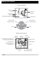
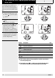
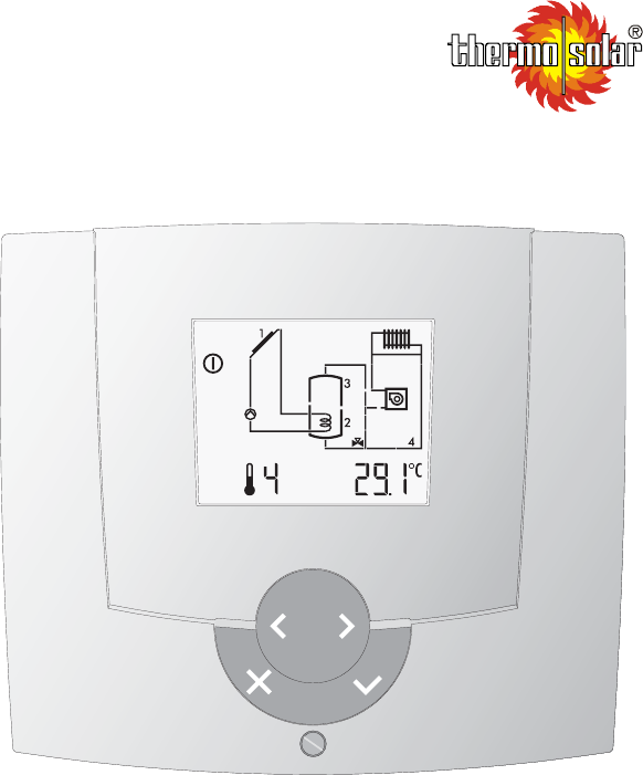
Display and controls Overview of display Operating mode Information Adjuster Hydraulic diagram SET Identification display value Display value Menu controll changing settings Menu controll changing settings Enter Cancel Display with all segments Sensor 1 collector 1 Sensor 4 collector 2 Diverting valve storage tank 2 Diverting valve exchanger Pump collector 2 Pump storeage tank 2 Pump collector 1 Heating system Auxillary heater Sensor 4 SET Storage tank 1 Sensor 2 A0805 Sensor 3 pump rehaet
Note:Display und Bedienelemente 4 A0805
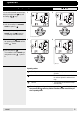
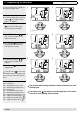
1 Operation 1.1 How to change operating modes You can select automatic or manuel operating by using the enter key and the settings keys. 1 2 Example: 1. when the controller is in automatic mode the symbol is . 2. To change the operating mode to manual, press the . enter key. The operating mode now flashes. 3. Press the settings key to select the operating mode manual until the symbol flashes. Automatic mode 3 4 4. Press the enter key .
1.2 The information menu, operating data and temperature value The information menu enables you to look at information about the solar system. You can see actual temperatures, and the way in wich the system is operating. 1 2 Example: 1. To enter the information menu, press the settings key until the symbol appears. 2. To look at the data, press the enter key. A value flashes on the display. 3. By pressing the settings key, the temperature values and operating data can seen in succession.
SET 1.3 Programming the controller In order to programm the controller you must enter the settings menu. 1 Example: 1. To enter the settings menu, press the settings key so often, until the symbol SET appears. 2 SET SET 2. To view the settings, press the enter key. The first setting and its function flashing on the display. Adjuster level 3. By pressing the settings keys, the various settings can by viewed in succession. 3 4.
SET 1.4 Making Basic Changes Adjuster HyFunction draulic 8-62 all Setting range Set temperature 1, normal 0÷90 Factory setting 60 Unit Basic setting Dat.: Revised Dat.: °C This anables you to set a set point temperature for the first circuit sensor. If the circuit is a hot water cylinder then the maximum temperature will be set at the point at wich the sensor contact enters the cylinder. Ther thermal circuit will only charge up to the value set here.
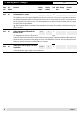
SET 1.5 Changes that need an access code (expert level) Certain changes should only be made by experts and are therefore this menu is protected by an access code. 1 Example: 1. To enter the expert menu keeping pressing the settings key so often, until the symbol SET appears. SET 2. To view the expert menu, press the enter key. The first intem that may be adjusted and its function flashes. 3. Keep pressing the settings until "Cod --" appears. 4. Press the enter code. key, 6.
SET 1.6 Adjuster code 1 Adjuster HyFunction draulic 04-06 all Hydraulic variants Setting range 1÷1 Factory setting Unit Basic setting Dat.: 1 - 16 - Revised Dat.: Hydraulic variant 1 = Speed (rpm) controlled collector pump on tank (SP) 1 04-20 all eBUS-Addressing 1÷16 Only ES 5911, not in use: Addressing the controller in eBUS combination. 16 standard master addresses.
SET 1.6 Adjuster code 1 Adjuster HyFunction draulic 08-15 all Setting range Start-up help on/off Factory setting on Unit Basic setting Dat.: Adaptation Dat.: - In some systems the collector temperature may not be properly recorded on start up. In the "on" position a sart up programm for the pump is activated enabling a very accurate reading to be taken by the sensor. In this programm the solar pump switches on for 30 seconds and then the pump switches off.
SET 1.6 Adjuster code 1 Adjuster HyFunction draulic 08-37 all Volume flow coll. pump 1 at 100% set value Setting range 1÷50 Factory setting 2 Unit Basic setting Dat.: Adaptation Dat.: l/min The volume flow at 100% set value of the pump collector 1 and aligned hydraulic. To calculate the volume flow in your system, you can take 1 l/min per collector. In manual operating mode set Adjuster 8-85 to 100%. Read the through-flow at the floating body volume flow meter.
SET 1.6 Adjuster code 1 Adjuster HyFunction draulic 08-55 all 08-59 all Tank type, tank 1 Setting range 0÷4 Factory setting 0 Unit Basic setting Dat.: Adaptation Dat.: - 0 = Hot water tank All charging strategies are possible. According to application, the settings for the change-over to alternating operation must be adjusted. (Adjuster 8-65 and Adjuster 8-66) 2 = Heating tank If the tank set value is set below 20°C, this is understood to be summer operation.
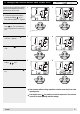
2 Dimensions and assembly 2.1 Dimensions DC 12 48.7 135.3 153.5 2.2 Dimensions of the basic housing DC 12 36 8 8.5 108 44 48 128 2.5 149 9.3 0.
2.3 Assembly DC 12 Determination of position of mounting The solar controller ES 5910/11 S is to be placed closely at the solar heating circle, so that a short wiring way is made possible. Open the controller for the assembly and wiring So that the controller base can be installed and wired, first it must be dismounted. 1. Loosen the screw of the front cover. 2. Take off the front cover. 3. With a screwdriver lift the base from the controller-print, see illustration right.
3 Start up The connections main voltage on the left side No. 1-3/LN are loaded with 230 V. These clamps may be affected only dead, otherwise mortal danger exists because of current impact.
SET Solar charging of tank 1. (Tank type can be chosen, warm water/ heating / swimming pool) 8-62 B2 Connections hydraulic 1: Sensors A0805 Factory setting Unit Basic set. Dat.
SET 3.3 Adjuster code 2 The adjusters with code 2 are valid for all hydraulic variants! You receive the code 2 from your heating expert. Adjuster Function 8-05 Overheating protection on/off on If the temperature at the collector rises above the set collector maximum temperature (Adjuster 8-11) with the overheating protection active, solar charging will be enabled independent of the set tank maximum temperature (Adjuster 8-59).
4 Troubleshooting If after switching on, no display appears, or an error message appears, the clarifications in following table can be useful. Statement Display doesn’t appear Possible cause Controller not under tension External switch is on position "Off" Wiring defect Solution Examine the fuse, set external switch to "ON"! Open the controller and examine the wiring! 4.1 Error codes Error-display Error Code 41 Hydraulic Description all Sensor 1 outside the measuring range.
4.2 Information about the plausibility check Info-display The controller checks the system status and signals errors. This is a plausibility check of the data and serves to provide information when malfunctioning occurs. Info code Hydraulic Description 101 all Collector max. temp. > as the collector protection Wrong basic settings temp.
5 Technical data DESIGNATION / TYPE DC 12 Voltage supply 230 V AC ± 10% 50 – 60 HZ Max. power input 2.3 VA Fuse 3.15 A OUTLETS Fully electronic relays 1 SWITCHING CAPACITY Fully electronic relays 1 (1) A Inputs sensor 2 Voltage, measuring circuit 12 V, V, protective insulation 4 kV HOUSING Montage Wall mounting Dimensions H / W / D 153.5x135.3x48.
Note: 22 A0805
6 Index A Adjuster code 1 ............................................................................................................................................10 Adjuster code 2 ............................................................................................................................................18 Adjuster with access code (expert level) ........................................................................................................9 Adjuster without code .............
Manufacture or distribution: Specially manufactured for Genersys Plc Genersys Plc, 37 Queen Anne Street London W1W 9JB Phone: 020 637 0901 Fax: 020 637 0908 Web: http://www.genersys.com enquiries@genersys.