
User`s guide

50
User’s Guide ADI-8 QS © RME
17.3 Latency and Monitoring
The term Zero Latency Monitoring has been introduced by RME in 1998 for the DIGI96 series
and describes the ability to pass-through the computer's input signal at the interface directly to
the output. Since then, the idea behind has become one of the most important features of mod-
ern hard disk recording. In the year 2000, RME published two ground-breaking Tech Infos on
the topics Low Latency Background, which are still up-to-date: Monitoring, ZLM and ASIO, and
Buffer and Latency Jitter, found on the RME website.
How much Zero is Zero?
From a technical view there is no zero. Even the analog pass-through is subject to phase er-
rors, equalling a delay between input and output. However, delays below certain values can
subjectively be claimed to be a zero-latency. This applies to analog routing and mixing, and in
our opinion also to RME's Zero Latency Monitoring. RME's digital receiver's buffer and the out-
put via the transmitter cause a typical delay of 3 samples. At 44.1 kHz this equals about 68 µs
(0.000068 s), at 192 kHz only 15 µs.
Oversampling
While the delays of digital interfaces can be disregarded altogether, the analog inputs and out-
puts do cause a significant delay. Modern converter chips operate with 64 or 128 times over-
sampling plus digital filtering, in order to move the error-prone analog filters away from the au-
dible frequency range as far as possible. This typically generates a delay of about 40 samples,
equalling one millisecond. A playback and re-record of the same signal via DA and AD (loop-
back) then causes an offset of the newly recorded track of about 2 ms.
Low Latency!
The ADI-8 QS uses high-class AD- and DA-converters from Cirrus Logic, offering exceptional
Signal to Noise and distortion figures. But the biggest difference to all other converter chips is
their innovative digital filter, achieving for the first time a delay of only 12 samples in Single
Speed, 9 samples in Double Speed, and 5 (!) samples in Quad Speed. The exact delays
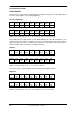
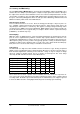
caused by the AD- and DA-conversion of the ADI-8 QS are:
Sample frequency kHz 44.1 48 88.2 96 176.4 192
AD (12 x 1/fs) ms 0.27 0.25
AD (9 x 1/fs) ms 0.1 0.09
AD (5 x 1/fs) ms 0.028 0.026
DA (10 x 1/fs) ms 0.22 0.2
DA (5 x 1/fs) ms 0.056 0.052
DA (5 x 1/fs) ms 0.028 0.026
These values are less than a quarter of those available from even much more expensive de-
vices. They represent an important step in further reducing the latency in the computer-based
recording studio. At Double Speed and Quad Speed the added latency can simply be ignored.
In short: the ADI-8 QS turns 'analog digital monitoring' into real analog-style monitoring.