User’s Guide ADI-8 QS The Professional’s Converter Solution ™ TotalRemote ™ FlexGain I64 Option Slot ™ SteadyClock ™ ® SyncCheck Professional 8-Channel AD/DA Converter Reference Low Latency Conversion 8-Channel Analog <> AES / ADAT Interface Optional 64-Channel MADI Interface 24 Bit / 192 kHz Digital Audio MIDI Remote Control AES-3 AES-10 24 Bit Interface
Important Safety Instructions ..................................4 General 1 2 3 4 Introduction ...............................................................6 Package Contents .....................................................6 Brief Description and Characteristics.....................6 First Usage – Quick Start 4.1 Controls - Connectors - Displays ............................7 4.2 Quick Start ..............................................................9 5 Accessories ...............................
Inputs and Outputs 11 12 13 14 15 Analog Inputs / Outputs 11.1 Line In .................................................................. 28 11.2 Line Out ............................................................... 29 Digital Inputs / Outputs 12.1 AES / EBU ........................................................... 30 12.2 ADAT Optical ....................................................... 31 12.3 I64 MADI Card ..................................................... 32 12.
Important Safety Instructions ATTENTION! Do not open chassis – risk of electric shock The unit has unisolated live parts inside. No user serviceable parts inside. Refer service to qualified service personnel. Mains • The device must be earthed – never use it without proper grounding • Do not use defective power cords • Operation of the device is limited to the manual • Use same type of fuse only To reduce the risk of fire or electric shock do not expose this device to rain or moisture.
User’s Guide ADI-8 QS General User’s Guide ADI-8 QS © RME 5
1. Introduction RME's ADI-8 QS is an 8-channel high-end AD/DA converter with a truly unique feature set. The device combines excellent analog circuit design with the latest generation of outstanding low latency AD/DA converter chips. Along with its integrated SteadyClock, the ADI-8 QS offers AD and DA conversion of the highest quality. When developing the ADI-8 QS we used all our experience, and also the experience of our customers, to create a unique, excellent and high-quality unit.
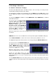
4. First Usage – Quick Start 4.1 Controls - Connectors - Displays The front of the ADI-8 QS features 16 LED level meters, nine select keys, one rotary encoder, and 30 LEDs providing a detailed status display. The analog input sensitivity can be changed in the area INPUT. Choosing DIG with the select key, the digital input signal is routed to the digital outputs, with the AD-conversion being deactivated.
The rear panel of the ADI-8 QS has eight analog inputs, eight analog outputs, mains power, a connector for the included Hardware Remote, MIDI I/O, word clock I/O, the I64 Option Slot, and all digital inputs and outputs (AES/ADAT). ANALOG INPUTS: Eight balanced Line inputs, 1/4" TRS inputs and D-sub. ANALOG OUTPUTS: Eight balanced Line outputs, 1/4" TRS outputs and D-sub. AES I/O (25-pin D-sub): The D-sub connector provides four AES/EBU outputs (AD signals) and four AES/EBU inputs (DA signals).
4.2 Quick Start After connection of all cables and power-on of the device, the configuration of the ADI-8 QS begins in the CLOCK section. Choose a clock source and a sample rate. Connect the TRS-jacks or the D-sub connector with the analog signal source. Change the input sensitivity by pressing INPUT until the input level is sufficient to avoid noisy operation. Try to achieve an optimum input level by adjusting the source itself.
5. Accessories RME offers several optional components for the ADI-8 QS: Part Number Description OK0050 OK0100 OK0200 OK0300 OK0500 OK1000 Optical cable, Toslink, 0.5 m (1.7 ft) Optical cable, Toslink, 1 m (3.3 ft) Optical cable, Toslink, 2 m (6.6 ft) Optical cable, Toslink, 3 m (9.9 ft) Optical cable, Toslink, 5 m 16.4 ft) Optical cable, Toslink, 10 m (32.8 ft) BO25MXLR4M4F1PRO Digital Breakout Cable Pro, AES/EBU 25-pin D-sub to 4 x XLR male + 4 x XLR female, 1m (3.3 ft) BO25MXLR4M4F3PRO same, 3 m (9.
6. Warranty Each individual ADI-8 QS undergoes comprehensive quality control and a complete test at IMM before shipping. The usage of high grade components allow us to offer a full two year warranty. We accept a copy of the sales receipt as valid warranty legitimation. If you suspect that your product is faulty, please contact your local retailer.
CE / FCC Compliance CE This device has been tested and found to comply with the limits of the European Council Directive on the approximation of the laws of the member states relating to electromagnetic compatibility according to RL89/336/EWG and RL73/23/EWG. FCC This equipment has been tested and found to comply with the limits for a Class A digital device, pursuant to Part 15 of the FCC Rules.
User’s Guide ADI-8 QS Usage and Operation User’s Guide ADI-8 QS © RME 13
8. Front Panel Controls 8.1 Input In the INPUT area, the select key causes a change of the analog input sensitivity, referenced to digital full scale level (0 dBFS) of the ADconverters. The choices are: +4.2 dBu (-10 dBV compatible), +13 dBu, +19 dBu and +24 dBu. As the adaptation is performed in the analog domain, the ADI-8 QS achieves the highest possible values for Signal to Noise ratio and distortion in any setting.
8.3 Input State The 8 level meter of the INPUT STATE show the digital value (dBFS) of the input level per channel. The level data incorporate Input Trim and Digital Limiter. The red LED OVR is lit 0.2 dB before full scale level (-0.2 dBFS). With activated METER GR AUTO the amount of Gain Reduction is shown in dB as bar from top to bottom, as soon as the Limiter becomes active.
44.1, 48 Activates the internal clock at 44.1 kHz or 48 kHz. DS, QS With the DS LED additionally lit, the sample rate will be 88.2 or 96 kHz, with QS lit it will be 176.4 or 192 kHz. A selection of DS and QS is also possible when using external clock (Slave). If the ADI-8 QS should operate at 192 kHz, but receives a synchronous word clock of 48 kHz, the button STATE allows to activate DS or QS mode.
8.10 Output In the OUTPUT area, the select key causes a change of the analog output level, referenced to digital full scale level (0 dBFS) of the DA-converters. The choices are: +4.2 dBu (-10 dBV compatible), +13 dBu, +19 dBu and +24 dBu. As the adaptation is performed in the analog domain, the ADI-8 QS achieves the highest possible values for Signal to Noise ratio and distortion ratio in any setting. 9. The Setup Menu Some options and settings are accessed and changed very seldomly.
When all LEDs of a column are turned off, the corresponding attenuation is: Channel 8 Channel 7 Channel 6 -6 dB -12 dB -18 dB Channel 5 Channel 4 Channel 3 -28 dB -40 dB -54 dB Channel 2 No LED -78 dB Mute When changing the Global Output Level the individual settings of Output Trim are maintained. So the gain of alll channels can be increased or decreased without them loosing their level relations. 9.3 Input Trim Default: 0 dB Available settings: 0 up to +6 dB in steps of 0.
When several ADI-8 QS, Micstasy or ADI-642 are connected via MADI, Auto ID normally takes care of the channel assignment (see chapter 9.7, Auto ID). In special cases, it may be desirable to set the ID manually, e.g. if the first device in a MADI chain does not support the Auto ID mode, or if a group of eight channels needs to be routed or processed in a particular way. With activated mode Digital to Digital ID also defines which MADI channels are sent to the ADAT/AES outputs, see chapter 9.15.
Units 2 3 4 5 6 7 8 Delay 3 6 9 12 15 18 21 Delay DS 6 12 18 - Delay QS 12 - DC 21 21 21 21 21 21 21 DC DS 18 18 18 - DC QS 12 - 21 samples @ 48 kHz equal 437 µs. 18 samples @ 96 kHz equal 187 µs. 12 samples @ 192 kHz equal 62.5 µs. As shown in the table, activating DC causes a constant delay of 21 samples in Single Speed, no matter how many devices are connected serially. In Double Speed the delay is 18, in Quad Speed 12 samples.
9.11 Trim Enable (TE) Default: On Available settings: On, Off The settings of the level calibration per channel, Input Trim and Output Trim (see chapter 9.3 and 9.4), can be deactivated globally. The gain is then set to 0 dB. The individual settings are not lost, changing between the calibrated (On) and the linear setting (Off) is possible back and forth anytime. 9.12 Global Output Level Enable (GE) Default: On Available settings: On, Off With the volume control deactivated the gain is fixed to 0 dB.
9.15 Digital to Digital (dd) Default: Direct Available settings: Direct, Effects The function Digital to Digital can operate in two ways. In mode Direct the digital input signal is sent with bit-accuracy to the digital outputs. In mode Effects the digital input signal is first processed by the digital settings Output Trim and Global Level, then by the Input Trim settings, then – when activated – by the digital limiter, before finally reaching the digital outputs.
10. Remote Control 10.1 Hardware Remote The included Hardware Remote offers direct access to the most important functions needed in a typical DAW workplace: • • • • Turning the VOL knob changes the volume (Global Output Level) Pushing the VOL knob activates DIM (Global Output Level -20 dB) Pushing the STORE button for 2 seconds stores the current level setting After changing the volume, RECALL sets the stored level value again Note: The Hardware Remote use the function Global Output Level, see chapter 9.
Unlike other MADI-based devices from RME, the ADI-8 QS is no bi-directional MIDI to MADI converter, because only one direction is available for the transmission. The block diagram shows the signal flow in a HDSP MADI-based remote control system. MIDI commands from a software on PC or Mac travel from the MADI Out of the HDSP MADI to the MADI In as well as to the MIDI Out and MADI Out of the ADI-8 QS.
Via MIDI remote control, all front panel controls of the ADI-8 QS can be locked (Lock Keys). An exception is the REMOTE key. In Off-state Lock Keys is deactivated. Therefore a locking of all the controls can be revoked directly at the unit at any time. The software MIDI Remote also controls RME's ADI-648, ADI6432, ADI-642, Micstasy and the MADI Bridge. A version for Mac OS X PPC and Intel is currently worked on.
User’s Guide ADI-8 QS © RME
User’s Guide ADI-8 QS Inputs and Outputs User’s Guide ADI-8 QS © RME 27
11. Analog Inputs / Outputs 11.1 Line In The ADI-8 QS rear has 8 balanced Line inputs, provided by 1/4" TRS and a 25-pin D-sub connector. Both are internally connected, so can not be used at the same time. The electronic input stage is built in a servo balanced design which handles unbalanced (mono jacks) and balanced (XLR, stereo jacks) signals correctly, automatically adjusting the level reference. When using unbalanced cables with XLR or TRS connectors be sure to connect pin 3 (- or ring) to 1 (ground).
11.2 Line Out The ADI-8 QS has 8 balanced Line outputs on the rear, provided by 1/4" TRS and a 25-pin D-sub connector. They have their own output drivers respectively and can therefore – in contrary to the inputs – be used simultaneously. The electronic output stage of the TRS jacks is built in a servo-balanced design which handles unbalanced (mono plugs) and balanced (stereo plugs) correctly, automatically adjusting the level reference. The maximum output level is +21 dBu.
12. Digital Inputs / Outputs 12.1 AES/EBU The four AES/EBU inputs and outputs are provided on the rear of the ADI-8 QS via a 25-pin Dsub connector with Tascam pinout (also used by Digidesign). A digital breakout cable will provide 4 male and 4 female XLR connectors. Every input and output is transformer-balanced and galvanically isolated. The inputs can be used in any combination, e. g. it is sufficient to connect an input signal only to input 3.
12.2 ADAT Optical The ADI-8 QS provides two digital inputs and outputs in ADAT optical format. Using sample rates up to 48 kHz only the port labeled MAIN is relevant for operation. Higher sample rates than 48 kHz are realized by sample multiplexing. When using more than four channels at Double Speed or two channels at Quad Speed, the port labeled AUX has to be used as well.
12.3 I64 MADI Card The I64 MADI Card provides the ADI-8 QS with a 64-channel MADI input and output. Coaxial and and optical output operate simultaneously and deliver the same data. The ID determines which MADI channels the ADI-8 QS will use (see chapter 9.5, ID). The MADI outputs operate in parallel to the AES/EBU and ADAT outputs, provide the same audio data, and are configured with the same front panel controls. The I64 MADI Card features an optical as well as a coaxial MADI input.
12.4 Differences serial MADI with I64 MADI Card and ADI-642 I64 MADI Card: Activate Auto ID in the first unit (ID of the master can be changed). All following units become Slave, get a consecutive ID, and with this the according channel routing. If desired, Delay Compensation has to be manually activated in each unit. ADI-642: Activate ADC (Auto Delay Compensation) in the first unit (ID of the master is always 1). All following units become Slave, and compensate the respective delay automatically.
13. Word Clock 13.1 Word Clock Input and Output Input The ADI-8 QS's transformer isolated word clock input is active when WCK is chosen in the clock section. The signal at the BNC input can be Single, Double or Quad Speed, the ADI-8 QS automatically adapts to it. As soon as a valid signal is detected, the WCK LED is constantly lit, otherwise it is flashing.
13.2 Operation and Technical Background In the analog domain one can connect any device to another device, a synchronization is not necessary. Digital audio is different. It uses a clock, the sample frequency. The signal can only be processed and transmitted when all participating devices share the same clock. If not, the signal will suffer from wrong samples, distortion, crackle sounds and drop outs.
13.3 Cabling and Termination Word clock signals are usually distributed in the form of a network, split with BNC T-adapters and terminated with resistors. We recommend using off-the-shelf BNC cables to connect all devices, as this type of cable is used for most computer networks. Actually you will find all the necessary components (T-adapters, terminators, cables) in most electronics and computer stores. The latter usually carries 50 Ohm components.
14. MIDI The ADI-8 QS has a standard MIDI input and output, a 5-pin DIN jack each. The MIDI I/O is used for: • remote control of the ADI-8 QS, see chapter 10.2 • transmission of MIDI data and remote control commands over MADI, in case the optional I64 MADI Card has been fitted, see chapter 10.3. 15. Remote This mini-DIN jack can only be used to connect the included remote control. The 5 meter (16 ft) long cable is fixed to the Hardware Remote unit.
User’s Guide ADI-8 QS © RME
User’s Guide ADI-8 QS Technical Reference User’s Guide ADI-8 QS © RME 39
15. Technical Specifications 15.1 Analog Line In 1-8, TRS/D-Sub • Input: 6.3 mm TRS jack and D-sub 25-pin, servo-balanced • Input impedance: 10 kOhm • Input sensitivity switchable +24 dBu, +19 dBu, +13 dBu, +4.2 dBu @ 0 dBFS Analog Limiter • Maximum analog input level unclipped: +30 dBu • Threshold On: -3 dBFS • Threshold Off: +3 dB • THD+N: 0.03%, -52 dB • Attack time: 3 ms • Release time: 2-step, digitally controlled AD-Conversion • Resolution: 24 bit • Signal to Noise ratio (SNR) @ +24 dBu, 44.
15.2 Digital Inputs AES/EBU • 4 x 25-pin D-sub, transformer-balanced, galvanically isolated, according to AES3-1992 • High-sensitivity input stage (< 0.3 Vpp) • SPDIF compatible (IEC 60958) • Accepts Consumer and Professional format • Lock Range: 27 kHz – 200 kHz • Jitter when synced to input signal: < 1 ns • Jitter suppression: > 30 dB (2.
15.3 Digital Outputs AES/EBU • 4 x, transformer-balanced, galvanically isolated, according to AES3-1992 • Output voltage Professional 4.0 Vpp • Format Professional according to AES3-1992 Amendment 4 • Single Wire: 4 x 2 channels 24 bit, up to 192 kHz ADAT • 2 x TOSLINK • Standard: 8 channels 24 bit, up to 48 kHz • S/MUX: 16 channels 24 bit / 48 kHz, equalling 8 channels 24 bit 96 kHz • S/MUX4: 16 channels 24 bit / 48 kHz, equalling 4 channels 24 bit 192 kHz Word Clock • BNC • Max.
15.6 General • • • • • • • • Power supply: Internal switching PSU, 100 - 240 V AC, 40 Watts Typical power consumption: 23 Watts Maximum power consumption: < 30 Watts Dimensions including rack ears (WxHxD): 483 x 44 x 242 mm (19" x 1.73" x 9.5") Dimensions without rack ears/handles (WxHxD): 436 x 44 x 235 mm (17.2" x 1.73" x 9.3") Weight: 3 kg ( 6.6 lbs) Temperature range: +5° up to +50° Celsius (41° F up to 122°F) Relative humidity: < 75%, non condensing 15.
15.9 Connector Pinouts D-Sub AES/EBU The D-sub connector provides four AES inputs and outputs. The pinout uses the widely spread Tascam scheme, which is also used by Digidesign. Tascam / Digidesign: Signal D-Sub Signal D-Sub In 1/2+ 24 In 1/212 In 3/4+ 10 In 3/423 In 5/6+ 21 In 5/69 In 7/8+ 7 In 7/820 Out 1/2+ 18 Out 1/26 Out 3/4+ 4 Out 3/417 Out 5/6+ 15 Out 5/63 Out 7/8+ 1 Out 7/814 GND is connected to pins 2, 5, 8, 11, 16, 19, 22, 25. Pin 13 is not connected.
D-Sub Analog Inputs / Outputs The 25 pin D-sub connectors of analog input and output are wired according to the Tascam scheme, as shown in this table: Channel D-sub 1+ 24 112 2+ 10 223 3+ 21 39 4+ 7 420 5+ 18 56 6+ 4 617 7+ 15 73 8+ 1 814 GND is connected to pins 2, 5, 8, 11, 16, 19, 22, 25. Pin 13 is unconnected. The servo balanced input circuitry allows to use unbalanced connections with no loss in level. For this to work, pins 3 (-) and 1 (GND) have to be connected.
16. Technical Background 16.1 Terminology Single Speed Sample rate range originally used in Digital Audio. Typical applications are 32 kHz (digital radio broadcast), 44.1 kHz (CD), and 48 kHz (DAT). Double Speed Doubles the original sample rate range, in order to achieve higher audio quality and improved audio processing. 64 kHz is practically never used, 88.2 kHz is quite rare in spite of certain advantages. 96 kHz is a common format. Sometimes called Double Fast.
16.2 Lock and SyncCheck Digital signals consist of a carrier and the data. If a digital signal is applied to an input, the receiver has to synchronize to the carrier clock in order to read the data correctly. To achieve this, the receiver uses a PLL (Phase Locked Loop). As soon as the receiver meets the exact frequency of the incoming signal, it is locked. This Lock state remains even with small changes of the frequency, because the PLL tracks the receiver's frequency.
16.3 Latency and Monitoring The term Zero Latency Monitoring has been introduced by RME in 1998 for the DIGI96 series and describes the ability to pass-through the computer's input signal at the interface directly to the output. Since then, the idea behind has become one of the most important features of modern hard disk recording.
16.4 DS - Double Speed When activating the Double Speed mode the ADI-8 QS operates at double sample rate. The internal clock 44.1 kHz turns to 88.2 kHz, 48 kHz to 96 kHz. The internal resolution is still 24 bit. Sample rates above 48 kHz were not always taken for granted, and are still not widely used because of the CD format (44.1 kHz) dominating everything. Before 1998 there were no receiver/transmitter circuits available that could receive or transmit more than 48 kHz.
16.6 AES/EBU - SPDIF The most important electrical properties of 'AES' and 'SPDIF' can be seen in the table below. AES/EBU is the professional balanced connection using XLR plugs. The standard is being set by the Audio Engineering Society based on the AES3-1992. For the 'home user', SONY and Philips have omitted the balanced connection and use either Phono plugs or optical cables (TOSLINK). The format called S/P-DIF (SONY/Philips Digital Interface) is described by IEC 60958.
16.7 Signal to Noise Ratio in DS- / QS-Operation The outstanding signal to noise ratio of the ADI-8 QS's AD-converters can be verified even without expensive test equipment, by using record level meters of various software. But when activating the DS and QS mode, the displayed noise level will rise from -114 dBFS to -110 dBFS at 96 kHz, and –79 dBFS at 192 kHz. This is not a failure.
16.8 MADI Basics MADI, the serial Multichannel Audio Digital Interface, has been defined already in 1989 as an extension of the existing AES3 standard following several manufacturers' wish. The format also known as AES/EBU, a balanced bi-phase signal, is limited to two channels. Simply put, MADI contains 28 of those AES/EBU signals in serial, i. e. after one another, and the sample rate can still even vary by +/-12.5%. The limit which cannot be exceeded is a data rate of 100Mbit/s.
16.9 SteadyClock The SteadyClock technology of the ADI-8 QS guarantees an excellent performance in all clock modes. Its highly efficient jitter suppression refreshes and cleans up any clock signal, and provides it as reference clock at the word clock output. Usually a clock section consists of an analog PLL for external synchronization and several quartz oscillators for internal synchronisation. SteadyClock requires only one quartz, using a frequency not equalling digital audio.
17.
18. MIDI Implementation ADI-8 QS 18.1 Basic SysEx Format Value F0h 00h 20h 0Dh 41h 00h..7Eh, 7Fh mm nn oo F7h Name SysEx header MIDITEMP manufacturer ID Model ID (ADI-8 QS) Bank number / device ID (7Fh = broadcast, all IDs) Message type Parameter number (see table 1) Databyte EOX Bank Number / Device ID The lower nibble refers to the device ID (0..7), the higher nibble refers to the bank number (0..7), e. g. 25h means bank 2, device 5. 7Fh adresses all banks and all devices. 18.
18.3 Table Set Val. Val. Resp. Databytes No. No. Name 00h 0 Output Level x x 01h 02h 03h 04h 05h 06h 07h 08h 09h 0Ah 0Bh 0Ch 0Dh 0Eh 0Fh 10h 11h 12h 13h 14h 15h 16h 17h 18h 19h 1Ah 1Bh 1Ch 1Dh 1 2 3 4 5 6 7 8 9 10 11 12 13 14 15 16 17 18 19 20 21 22 23 24 25 26 27 28 29 Trim Output Ch. 1 Trim Output Ch. 2 Trim Output Ch. 3 Trim Output Ch. 4 Trim Output Ch. 5 Trim Output Ch. 6 Trim Output Ch. 7 Trim Output Ch. 8 Trim Input Ch. 1 Trim Input Ch. 2 Trim Input Ch. 3 Trim Input Ch. 4 Trim Input Ch.
Setup 1 Setup 2 Setup 3 Setup 4 Setup 5 MSB / 7 6 5 4 3 2 1 LSB / 0 MSB / 7 6 5 4 3 2 1 LSB / 0 MSB / 7 6 5 4 3 2 1 LSB / 0 MSB / 7 6 5 4 3 2 1 LSB / 0 MSB / 7 6 5 4 3 2 1 LSB / 0 MSB / 2 1 LSB / 0 MSB / 1 LSB / 0 MSB / 1 LSB / 0 0 analog input: 0 = +4dBu, 1 = +13dBu, 2 = +19dBu analog input: 3 = +24dBu, 4 = dig.
Lock / Sync 1 (Request only) (Request only) (Request only) (Request only) Lock / Sync 2 (Request only) (Request only) (Request only) (Request only) Lock / Sync 3 (Request only) (Request only) (Request only) (Request only) MSB / 7 6 5 4 3 2 1 LSB / 0 0 0 0 0 WCK Sync: 0 = no sync, 1 = sync WCK Lock: 0 = unlock, 1 = lock Option Sync: 0 = no sync, 1 = sync Option Lock: 0 = unlock, 1 = lock MSB / 7 6 5 4 3 2 1 LSB / 0 0 0 ADAT 1 Sync: 0 = no sync, 1 = sync ADAT 1 Lock: 0 = unlock, 1 = lock ADAT 2 Sync: 0