
User`s guide

User’s Guide DMC-842 © RME
31
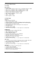
14. Digital Outputs
14.1 AES/EBU
The four AES/EBU outputs are provided on the rear of the DMC-842 via a 25 pin D-sub connec-
tor with Tascam pinout (also used by Digidesign). A digital breakout cable will provide 4 male
(and 4 female) XLR connectors. Every output is transformer-balanced, ground-free and com-
patible to all devices with AES/EBU ports.
In normal operation the AES outputs carry the converted analog input signal. When using the
I64 MADI Card and activating the option oP in the Setup menu do, the MADI input data is pre-
sent at the output instead, see chapter 11.11.
Besides the audio data, digital signals in SPDIF or AES/EBU format contain a channel status
coding, which is being used for transmitting further information. The output signal coding of the
DMC-842 has been implemented according to AES3-1992 Amendment 4:
• 32 kHz, 44.1 kHz, 48 kHz, 64 kHz, 88.2 kHz, 96 kHz, 176.4 kHz, 192 kHz according to the
current sample rate
• Audio use
• No Copyright, Copy permitted
• Format Professional
• Category General, Generation not indicated
• 2-Channel, No Emphasis
• Aux bits audio use, 24 bit
• Origin: DMC8
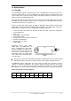
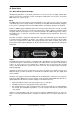
Connecting devices with coaxial
SPDIF ports to the DMC-842's out-
puts is accomplished by simple cable
adapters XLR/RCA. To achieve this,
pins 2 and 3 of an XLR plug are being
connected to the two contacts of a
Phono/RCA plug. The ground shield
of the cable is only connected to pin 1
of the XLR plug.
Note that most consumer HiFi equipment with phono SPDIF inputs will only accept signals
with Channel Status ‘Consumer’! In such cases the above adapter cable will not work.
The DMC-842 supports Single Wire only, in the range of 32 kHz up to 192 kHz: a total of 8
channels, 2 channels per AES wire. The effective sample frequency equals the clock on the
AES wire. In case a conversion from/to Single, Double and Quad Wire is required, the RME
ADI-192 DD, an 8-channel universal sample rate and format converter, is highly recommended.
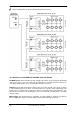
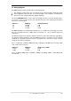
Pinout of the D-sub connector, Outputs
Signal Out
1/2+
Out
1/2-
Out
3/4+
Out
3/4-
Out
5/6+
Out
5/6-
Out
7/8+
Out
7/8-
D-Sub 18 6 4 17 15 3 1 14
GND is connected to pins 2, 5, 8, 11, 16, 19, 22, 25. Pin 13 is not connected.