
User`s guide

User’s Guide DMC-842 © RME
43
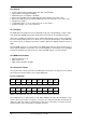
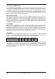
Yamaha:
Signal In
1/2+
In
1/2-
In
3/4+
In
3/4-
In
5/6+
In
5/6-
In
7/8+
In
7/8-
D-Sub 1 14 2 15 3 16 4 17
Signal Out
1/2+
Out
1/2-
Out
3/4+
Out
3/4-
Out
5/6+
Out
5/6-
Out
7/8+
Out
7/8-
D-Sub 5 18 6 19 7 20 8 21
GND is connected to pins 9, 10, 11, 12, 13, 22, 23, 24, 25.
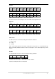
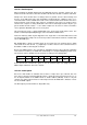
The same is true for a direct adapter cable Tascam D-sub to Euphonix D-sub.
Euphonix:
Signal In
1/2+
In
1/2-
In
3/4+
In
3/4-
In
5/6+
In
5/6-
In
7/8+
In
7/8-
D-Sub 15 2 4 16 18 5 7 19
Signal Out
1/2+
Out
1/2-
Out
3/4+
Out
3/4-
Out
5/6+
Out
5/6-
Out
7/8+
Out
7/8-
D-Sub 21 8 10 22 24 11 13 25
GND is connected to pins 3, 6, 9, 12, 14, 17, 20, 23. Pin 1 is not connected.
XLR sockets
The XLR connectors are wired according to international standards:
1 = GND (shield)
2 = + (hot)
3 = - (cold)
Note on the analog outputs: The output circuitry does not operate in a servo-balanced way.
When connecting unbalanced devices make sure that pin 3 of the XLR output stays uncon-
nected.
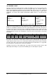
RS-232
The 9-pin D-Sub Connector is wired according to industry standard:
Signal In (Rx) Out (Tx) GND NC
Sub-D 2 3 5 9
Internally connected are pins 1 with 6 and 4, and pin 7 with 8.
Note that currently RS-232 is not functional.