User's Guide Fireface 400 Portable FireWire® at its best! ™ TotalMix FX 24 Bit / 192 kHz 9 ™ SyncAlign ZLM ™ ™ SyncCheck ™ SteadyClock FireWire 400 Digital I/O System 8 + 8 + 2 Channels Analog / ADAT / SPDIF Interface 24 Bit / 192 kHz Digital Audio 36 x 18 Matrix Router MIDI I/O Stand-Alone Operation MIDI Remote Control Stand-Alone MIDI Controlled Operation
General 1 2 3 4 5 Introduction ...............................................................6 Package Contents .....................................................6 System Requirements ..............................................6 Brief Description and Characteristics.....................6 First Usage - Quick Start 5.1 Connectors and Front Panel ...................................7 5.2 Quick Start ..............................................................
17 18 19 Using more than one Fireface ............................... 35 DIGICheck Mac........................................................ 36 Hotline – Troubleshooting ..................................... 37 Stand-Alone Operation, Connections 20 Stand-alone Operation 20.1 Front Panel Operation ......................................... 40 20.2 8-channel AD/DA-Converter ................................ 41 20.3 2-channel Mic Preamp......................................... 41 20.4 Monitor Mixer ........
27 TotalMix Super-Features 27.1 ASIO Direct Monitoring (Windows only) ..............72 27.2 Copy a Submix.....................................................72 27.3 Delete a Submix...................................................72 27.4 Doubling the Output Signal ..................................72 27.5 Recording a Subgroup (Loopback)......................73 27.6 MS Processing .....................................................74 28 MIDI Remote Control 28.1 Overview ..................................
User's Guide Fireface 400 General User's Guide Fireface 400 © RME 5
1. Introduction Thank you for choosing the Fireface 400. This unique audio system is capable of transferring analog and digital audio data directly to a computer from practically any device. The latest Plug and Play technology guarantees a simple installation, even for the inexperienced user. The numerous unique features and well thought-out configuration dialog puts the Fireface 400 at the very top of the range of computer-based audio interfaces.
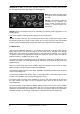
5. First Usage – Quick Start 5.1 Connectors and Front Panel The front of the Fireface 400 features instrument, microphone and line inputs, a stereo line/headphone output, a rotary encoder with 7 segment display, and several status and MIDI LEDs. The Neutrik combo jacks of the Mic/Line inputs can be used with both XLR and 1/4" TRS plugs. Both inputs display overload (CLIP), signal presence (SIG) and activated phantom power (48V) via green, red and yellow LEDs.
Word Clock I/O (BNC): A push switch activates internal termination (75 Ohms). When termination is activated the yellow LED besides the switch lights up. MIDI I/O: Provides two MIDI inputs and outputs via the included breakout cable. FW 400: 6-pin FireWire sockets for connection to the computer. The second socket provides hub functionality, to connect another FireWire device. POWER (switch): The Fireface 400 can be powered by an external power supply (EXT.) or via FireWire (BUS).
User's Guide Fireface 400 Installation and Operation - Windows User's Guide Fireface 400 © RME 9
6. Hardware and Driver Installation 6.1 Hardware and Driver Installation To simplify installation it is recommended to first install the drivers before the unit is connected to the computer. But it will also work the other way round. Insert the RME Driver CD into your CD-ROM drive. The driver installer is located in the directory \Fireface_FW. Start rmeinstaller.exe and follow the instructions of the installer. After installation connect computer and Fireface 400 using the supplied FireWire cable.
7. Configuring the Fireface 7.1 Settings dialog - General Configuration of the Fireface 400 is done via its own settings dialog. 'Settings' can be opened: • by clicking on the fire symbol in the Task Bar's system tray The mixer of the Fireface 400, TotalMix FX, can be opened: • by clicking on the mixer icon in the Task Bar's notification area The hardware of the Fireface 400 offers a number of practical functions and options which affect how the card operates.
Enable MMCSS for ASIO activates support with higher priority for the ASIO driver. Note: At this time, activating this option seems to be useful only with the latest Cubase/Nuendo at higher load. With other software this option can decrease performance. The change becomes active after an ASIO reset. Therefore it is easy to quickly check which setting works better..
Clock Mode Sample Rate Sets the currently used sample rate. Offers a central and comfortable way of configuring the sample rate of all WDM devices to the same value, as since Vista this is no longer supported to be done by the audio program. However, an ASIO program can still set the sample rate by itself. At ongoing record/playback the selection is grayed out, so no change is possible.
7.2 Settings Dialog – Analog Level Line In Defines the reference level of the rear analog inputs 5-8. The available settings are -10 dBV, +4 dBu and LoGain. Line Out Defines the reference level of the rear analog outputs 1-6. The available settings are -10 dBV, +4 dBu and HiGain. Phones Defines the reference level of the analog outputs 7/8. The available settings are -10 dBV, +4 dBu and HiGain.
7.3 Settings dialog - Pitch Usually soundcards and audio interfaces generate their internal clock (master mode) by a quartz. Therefore the internal clock can be set to 44.1 kHz or 48 kHz, but not to a value in between. SteadyClock, RME's Low Jitter Clock System, is based on a Direct Digital Synthesizer (DDS). This superior circuitry can generate nearly any frequency with highest precision.
7.4 Settings Dialog - LTC The Fireface 400 can extract position information as APP (ASIO Positioning Protocol) from Timecode (LTC, SMPTE) received at the analog input 4. A detected Timecode is shown as time information in the LTC In field. The analog input signal needs a specific level: slowly reduce the level until the display stumbles or completely fails. Then increase the level by about 10 dB. The field Input State will show further details of the Timecode.
Under WDM the Fireface will (has to) set the sample rate. Therefore the error shown to the right can occur. A stable signal with a sample rate of 32 kHz is detected at the ADAT input (Sync), but Windows audio had been set to 44100 Hz before. The red color of the text label signals the error condition, and prompts the user to set 32000 Hz manually as sample rate. Under ASIO the audio software sets the sample rate, so that such an error can not happen.
8. Operation and Usage 8.1 Playback In the audio application being used, Fireface must be selected as output device. This can often be found in the Options, Preferences or Settings menus under Playback Device, Audio Devices, Audio etc. We recommend switching all system sounds off (via >Control Panel /Sound<). Also Fireface should not be the Preferred Device for playback, as this could cause loss of synchronization and unwanted noises.
8.2 DVD-Playback (AC-3/DTS) When using popular DVD software players like WinDVD and PowerDVD, their audio data stream can be sent to any AC-3/DTS capable receiver using the Fireface's SPDIF outputs. For this to work, the WDM SPDIF device of the Fireface 400 has to be selected in >Control Panel/ Sounds and Multimedia/ Audio< or >Control Panel/ Sound/Playback<. Also check 'use preferred device only'. The DVD software's audio properties now show the options 'SPDIF Out' or similar.
8.3 Notes on WDM The driver offers one WDM streaming device per stereo pair, like ADAT 1+2 (Fireface 400). WDM Streaming is Microsoft's current driver and audio system, directly embedded into the operating system. WDM Streaming is hardly usable for professional music purposes, as all data is processed by the so called Kernel Mixer, causing a latency of at least 30 ms.
8.4 Channel Count under WDM The Fireface’s ADAT optical interface offers sample rates of up to 96 kHz using a standard ADAT recorder. For this to work single-channel data is spread to two ADAT channels using the Sample Multiplexing technique. This reduces the number of available ADAT channels from 8 to 4 per ADAT port. Whenever the Fireface 400 changes into Double Speed (88.2/96 kHz) or Quad Speed mode (176.4/192 kHz) all unusable devices are automatically removed.
8.6 Digital Recording Unlike analog soundcards which produce empty wave files (or noise) when no input signal is present, digital interfaces always need a valid input signal to start recording. Taking this into account, RME added a comprehensive I/O signal status display showing sample frequency, lock and sync status in the Settings dialog, and status LEDs for each input to the Fireface 400.
9. Operation under ASIO 9.1 General Start the ASIO software and select ASIO Fireface as the audio I/O device. Fireface 400 supports ASIO Direct Monitoring (ADM). The Fireface 400 supports both MME MIDI and DirectMusic MIDI. 9.2 Channel Count under ASIO At a sample rate of 88.2 or 96 kHz, the ADAT optical input and outputs operate in S/MUX mode, so the number of available channels per port is reduced from 8 to 4.
9.3 Known Problems If a computer does not provide sufficient CPU-power and/or sufficient FireWire transfer rates, then drop outs, crackling and noise will appear. Such effects can be avoided by using a higher buffer setting/latency in the Settings dialog of the Fireface 400. Furthermore PlugIns should be deactivated temporarily to make sure they do not cause these problems. More information can be found in chapter 30.3. Another common source of trouble is incorrect synchronization.
• The driver has no control on the numbering of the WDM devices. Therefore it might happen that the WDM devices (2) are mapped to unit (1), especially when switching on more Firefaces during a Windows session. A reboot with all Firefaces already operational should solve this problem. Note: TotalMix is part of the hardware of each Fireface. Up to three mixers are available, but these are separated and can't interchange data. Therefore a global mixer for all units is not possible. 11.
12. Hotline – Troubleshooting The newest information can always be found on our website www.rme-audio.com, section FAQ, Latest Additions. The input signal cannot be monitored in real-time • ASIO Direct Monitoring has not been enabled, and/or monitoring has been disabled globally. The 8 ADAT channels don’t seem to work • The optical output has been switched to 'SPDIF'.
User's Guide Fireface 400 Mac OS X – Installation and Operation User's Guide Fireface 400 © RME 27
13. Hardware Installation • Connect computer and Fireface using the supplied 6-pin FireWire cable (IEEE1394a). • Connect the power supply to the Fireface and then to any suitable power outlet. • Power-on the computer. 14. Driver and Firmware 14.1 Driver Installation After the Fireface has been connected (see 13. Hardware Installation), install the drivers from the RME Driver CD. The driver files are located in the folder Fireface_FW. Installation works automatically by a double-click on the file fireface.
14.3 Firmware Update The Flash Update Tool updates the firmware of the Fireface 400 to the latest version. It requires an already installed driver. Start the program Fireface Flash. The Flash Update Tool displays the current revision of the Fireface firmware, and whether it needs an update or not. If so, simply press the 'Update' button. A progress bar will indicate when the flash process is finished (Verify Ok).
15. Configuring the Fireface 15.1 Settings Dialog - General Configuring the Fireface 400 is done via its own settings dialog. Start the program Fireface Settings. The mixer of the Fireface (TotalMix FX) can be configured by starting the program Totalmix. The Fireface’s hardware offers a number of helpful, well thought-of practical functions and options which affect how the card operates - it can be configured to suit many different requirements.
Analog Inputs 1 Mic, 2 Mic Gain setting for the microphone preamps of input 1 and 2. The current gain is displayed in dB to the left of the fader. Phantom power (48V) can be selected for each microphone input separately. The option Link simplifies the setup in case both channels shall have the same setting/values. In the lower range the fader jumps from 10 dB to 0 dB. This useful additional setting allows to operate even line signals with the microphone input (up to +10 dBu).
Word Clock Out The word clock output signal usually equals the current sample rate. Selecting Single Speed causes the output signal to always stay within the range of 32 kHz to 48 kHz. So at 96 kHz and 192 kHz sample rate, the output word clock is 48 kHz. Sample Rate Used to set the current sample rate. This is the same setting as in the Audio MIDI Setup, just added here for your convenience. System Clock Shows the current clock state of the Fireface 400.
15.2 Clock Modes - Synchronization In the digital world, all devices must be either Master (clock source) or Slave (clock receiver). Whenever several devices are linked there must always be a single master clock. A digital system can only have one master! If the Fireface’s clock mode is set to 'Internal', all other devices must be set to ‘Slave’. The Fireface 400 utilizes a very user-friendly, intelligent clock control, called AutoSync.
16. Mac OS X FAQ 16.1 MIDI doesn't work In some cases MIDI does not work after the installation of the Fireface driver. To be precise, applications do not show an installed MIDI port. The reason for this is usually visible within the Audio MIDI Setup. It displays no RME MIDI device, or the device is greyed out and therefore inactive. Mostly, removing the greyed out device and searching for MIDI devices again will solve the problem.
16.5 FireWire Compatibility RME's Fireface 400 should be fully compatible to any FireWire port found on Apple Mac computers. An exception are MacBook, MacBook Pro and iMac from 2007 up to 2009 with Agere FireWire chip revision 6 (FW643). Although we tested compatibility with lots of models, total compatibility can not be guaranteed. In case of trouble please contact RME support. 16.6 Various Information The current driver of the Fireface 400 requires 10.6 or higher.
18. DIGICheck Mac The DIGICheck software is a unique utility developed for testing, measuring and analysing digital audio streams. Although this Windows software is fairly self-explanatory, it still includes a comprehensive online help. DIGICheck 0.683 operates in parallel to any software, showing all input data. The following is a short summary of the currently available functions: • Level Meter. High precision 24-bit resolution, 2/10/18 channels.
19. Hotline – Troubleshooting The newest information can always be found on our website www.rme-audio.com, section FAQ, Latest News. The unit and drivers have been installed correctly, but playback does not work: • Is Fireface 400 listed in the System Profiler? (Vendor ID 2613). • Has Fireface been selected as current playback device in the audio application? The 8 ADAT channels don’t seem to work • The optical output has been switched to 'SPDIF'.
User's Guide Fireface 400 © RME
User's Guide Fireface 400 Stand-Alone Operation, Connections User's Guide Fireface 400 © RME 39
20. Stand-alone Operation The Fireface 400 has an internal memory to permanently store all configuration data. These are: Settings dialog Sample rate, clock mode Master/Slave, configuration of the channels and the digital I/Os. TotalMix The complete mixer state. The Fireface loads those settings directly after power-on. A simple, yet useful application is to store the correct clock mode, avoiding wrong clocking and noise disturbances in a complex setup, caused by wrong synchronization.
L.1 bis L.6, PH, SP, A.1 bis A.8 The output levels of these outputs can be defined in the range +6 dB down to –58 dB in steps of 1 dB. Additionally the setting maximum attenuation (Mute) is available. The gain change is performed digitally by TotalMix. Stereo Mode Pushing the knob for more than a second activates the Link (Gang) mode. The display will show off or on. In stereo (on) mode, the display only presents the left channels of a stereo pair (L1, L3, L5...).
21. Analog Inputs 21.1 Line Rear The Fireface has balanced line inputs as 1/4" TRS jacks on the back of the unit. The electronic input stage is built in a servo balanced design which handles unbalanced (mono jacks) and balanced (stereo jacks) correctly, automatically adjusting the level reference. When using unbalanced cables with TRS jacks: be sure to connect the 'ring' contact of the TRS jack to ground. Otherwise noise may occur, caused by the unconnected negative input of the balanced input.
21.3 Instrument / Line Front The instrument inputs 3/4 of the Fireface 400 are exceptionally flexible. Several gain and impedance options make them the ideal receivers for both line and instrument signals. Line Inputs 3/4 have balanced line inputs as 1/4" TRS jacks. The electronic input stage is built in a servo balanced design which handles unbalanced (mono jacks) and balanced (stereo jacks) correctly, automatically adjusting the level reference.
22. Analog Outputs 22.1 Line The eight short circuit protected, low impedance line outputs are available as 1/4" TRS jacks on the back of the unit. The electronic output stage is built in a servo balanced design which handles unbalanced (mono jacks) and balanced (stereo jacks) correctly.
23. Digital Connections 23.1 ADAT The ADAT optical input of the Fireface 400 is fully compatible with all ADAT optical outputs. RME's unsurpassed Bitclock PLL prevents clicks and drop outs even in extreme varipitch operation, and guarantees a fast and low jitter lock to the digital input signal. A usual TOSLINK cable is sufficient for connection. More information on Double Speed (S/MUX) can be found in chapter 30.5. ADAT In Interface for a device sending an ADAT signal to the Fireface 400.
The Fireface’s new output header is optimized for largest compatibility with other digital devices: • 32 kHz, 44.1 kHz, 48 kHz, 88.2 kHz, 96 kHz, 176.
24. Word Clock 24.1 Word Clock Input and Output SteadyClock guarantees an excellent performance in all clock modes. Based on the highly efficient jitter suppression, the Fireface refreshes and cleans up any clock signal, and provides it as reference clock at the BNC output (see section 36.9). Input The Fireface's word clock input is active when Pref. Sync Ref in the Settings dialog has been switched to Word Clock, the clock mode AutoSync has been activated, and a valid word clock signal is present.
24.2 Technical Description and Usage In the analog domain one can connect any device to another device, synchronisation is not necessary. Digital audio is different. It uses a clock, the sample frequency. The signal can only be processed and transmitted when all participating devices share the same clock. If not, the signal will suffer from wrong samples, distortion, crackle sounds and drop outs. AES/EBU, SPDIF and ADAT are self-clocking, an additional word clock connection in principle isn't necessary.
24.3 Cabling and Termination Word clock signals are usually distributed in the form of a network, split with BNC T-adapters and terminated with resistors. We recommend using off-the-shelf BNC cables to connect all devices, as this type of cable is used for most computer networks. You will find all the necessary components (T-adapters, terminators, cables) in most electronics and/or computer stores. The latter usually carries 50 Ohms components.
User's Guide Fireface 400 © RME
User's Guide Fireface 400 TotalMix FX User's Guide Fireface 400 © RME 51
25. TotalMix: Routing and Monitoring 25.1 Overview The Fireface 400 includes a powerful digital real-time mixer, the Fireface mixer, based on RME’s unique, sample-rate independent TotalMix technology. It allows for practically unlimited mixing and routing operations, with all inputs and playback channels simultaneously, to any hardware outputs. Here are some typical applications for TotalMix: • Setting up delay-free submixes (headphone mixes).
User's Guide Fireface 400 © RME 53
25.2 The User Interface The visual design of the TotalMix mixer is a result of its capability to route hardware inputs and software playback channels to any hardware output. The Fireface 400 provides 18 input channels, 18 software playback channels, and 18 hardware output channels: TotalMix can be used in the above view (View Options 2 Row).
25.3 The Channels A single channel can be switched between mono and stereo mode. The mode is set in the channel settings. Hardware Outputs are always stereo. Channel name. The name field is the preferred place to select a channel by a mouse click. A double click opens a dialog to assign a different name. The original name will be shown when activating the option Names in the View Options. Panorama. Routes the input signal freely to the left and right routing destination (lower label, see below).
The lowest field shows the current routing target. A mouse click opens the routing window to select a routing target. The list shows all activated routings of the current channel by arrows in front of the listed entries, the current one is shown in bold letters. An arrow is only shown with an activated routing. A routing is seen as activated when audio data is sent. As long as the fader is set to −∞ the current routing will be shown in bold letters, but not have an arrow in the front. Trim Gain.
A click on the tool symbol opens the channel’s Settings panel. Stereo. Switches the channel to mono or stereo mode. Width. Setting the stereo width. 1.00 equals full stereo, 0.00 mono, 1.00 swapped channels. MS Proc. Activates M/S processing within the stereo channel. Monaural information is sent to the left channel, stereo information to the right. Phase L. Inverts the phase of the left channel by 180°. Phase R. Inverts the phase of the right channel by 180°.
25.4 Section Control Room In the section Control Room the menu Assign is used to define the Main Out which is used for listening in the studio. For this output the functions Dim, Recall, Mono and Talkback are automatically applied. Additionally the channel will be shifted from the Hardware Outputs into the Control Room section, and renamed Main. The same happens when assigning Main Out B or the Phones. The original name can be displayed by the function Names in the View Options at any time.
25.5 The Control Strip The Control Strip on the right side is a fixed element. It combines different functions that are either required globally, or constantly used, and therefore should not be hidden in a menu. Device selection. Select the unit to be controlled in case more than one is installed on the computer. Undo / Redo. With the unlimited Undo and Redo changes of the mix can be undone and redone, at any time. Undo/Redo does not cover graphical changes (window size, position, channels wide/narrow etc.
25.5.1 View Options View Options - Show. This area combines different functions of routing, the level meters and the mixer view. Routing Mode ¾ Submix: The Submix view (default) is the preferred view and delivers the quickest overview, operation and understanding of TotalMix. The click on one of the Hardware Output channels selects the respective submix, all other outputs are darkened. At the same time all routing fields are set to this channel.
25.5.2 Snapshots - Groups Snapshots. Snapshots include all mixer settings, but no graphical elements like window positions, window size, number of windows, visible settings, scroll states etc. Only the state wide/narrow of the channels is registered. Moreover the Snapshot is only temporarily stored. Loading a Workspace causes the loss of all stored Snapshots, when these all had not been saved before in a Workspace, or separately via File / Save Snapshot as.
Hidden channels in Mixer/Matrix are still fully functional. An existing routing/mixing/FX processing stays active. But as the channel is no longer visible it can not be edited anymore. At the same time the hidden channels are removed from the list of remote controllable channels, to prevent them from being edited unnoticed. Hidden channels in MIDI Remote x are removed from the list of remote controllable channels. Within an 8-channel block of a Mackie compatible control they are skipped.
The button Sub activates another useful special view. When in Submix view, Sub will cause all channels to disappear that are not part of the currently selected Submix/Hardware Output. Sub temporarily shows the mix based on all channels from Inputs and Playback row, independent from the current Layout Preset. That makes it very easy to see and to verify which channels are mixed/routed to the current output.
25.6 Preferences The dialog Preferences can be opened via the Options menu or directly via F2. Level Meters ¾ Full scale samples for OVR. Number of consecutive samples to trigger an over detection (1 to 10). ¾ Peak Hold Time. Hold time of the peak value. Adjustable from 0.1 up to 9.9 s. ¾ RMS +3 dB. Shifts the RMS value by +3 dB, so that full scale level is identical for Peak and RMS at 0 dBFS. Mixer Views ¾ FX Send follows highest Submix. Not available for the Fireface 400.
25.6.1 Store for Current or All Users (Windows) TotalMix FX stores all settings, workspaces and snapshots for the current user in: XP: C:\Documents and Settings\ Username\Local Settings\ Application Data\TotalMixFX Vista/7/8: C.\Users\Username\AppData\Local\TotalMixFX Current User ensures that when workstations are used by several people they all find their own settings. In case the settings should be identical or given for any user, TotalMix FX can be changed to use the All User directory.
25.7.2 MIDI Page The MIDI page has four independent settings for up to four MIDI remote controls, using CC commands or the Mackie Control protocol. Index Select one of four settings pages and thus remote controls. Settings are remembered automatically. To activate or deactivate any of the four remote controls check or uncheck ‘In Use’. MIDI Remote Control ¾ MIDI In. Input where TotalMix receives MIDI Remote data. ¾ MIDI Out. Output where TotalMix sends MIDI Remote data. ¾ Disable MIDI in background.
25.7.3 OSC Page The OSC page has four independent settings for up to four MIDI remote controls via Open Sound Control (OSC). This is a network based remote protocol that can be used for example by Apple’s iPad with the app TouchOSC or Lemur to wirelessly remote control TotalMix FX running on a Mac or Windows computer. Index Select one of four settings pages and thus remote controls. Settings are remembered automatically. To activate or deactivate any of the four remote controls check or uncheck ‘In Use’.
25.7.4 Aux Devices The RME OctaMic XTC is a highly flexible hi-quality 8-channel microphone, line and instrument preamp with integrated AD-conversion to ADAT, AES/EBU and MADI, plus 4 channels of DAconversion for monitoring. It can be used as universal front-end for the Fireface 400 and other interfaces. To simplify operation the most important parameters of the XTC (gain, 48V, phase, mute, AutoSet) can be controlled directly from the TotalMix FX input channels.
25.8 Hotkeys and Usage TotalMix FX has many hotkeys and mouse/hotkey combinations to speed up and simplify the usage. The Shift key enables a fine-tuning of the gain with all faders and in the Matrix. On all knobs it will speed up the setting. A click on a fader with held down Shift key adds the fader to the temporary fader group. A click in the fader path with held down Ctrl key will let the fader jump to 0 dB, at the next click to −∞. Same function: Double click of the mouse.
25.9 Menu Options Deactivate Screensaver: When active (checked) any activated Windows screensaver will be disabled temporarily. Always on Top: When active (checked) the TotalMix window will always be on top of the Windows desktop. Note: This function may result in problems with windows containing help text, as the TotalMix window will even be on top of those windows, so the help text isn't readable. Enable MIDI / OSC Control: Activates external MIDI control of the TotalMix mixer.
26. The Matrix 26.1 Overview The mixer window of TotalMix looks and operates similar to mixing desks, as it is based on a conventional stereo design. The matrix display presents a different method of assigning and routing channels, based on a single channel or monaural design. The matrix view of the Fireface 400 has the look and works like a conventional patchbay, adding functionality way beyond comparable hardware and software solutions.
The Matrix not always replaces the mixer view, but it significantly enhances the routing capabilities and - more important - is a brilliant way to get a fast overview of all active routings. It shows you in a glance what's going on. And since the Matrix operates monaural, it is very easy to set up specific routings with specific gains. 27. Tips and Tricks 27.1 ASIO Direct Monitoring (Windows) Programs that support ADM (ASIO Direct Monitoring - Samplitude, Sequoia, Cubase, Nuendo etc.
27.5 Recording a Subgroup (Loopback) TotalMix includes an internal loopback function, from the Hardware Outputs to the recording software. Instead of the signal at the hardware input, the signal at the hardware output is sent to the record software. This way, submixes can be recorded without an external loopback cable. Also the playback from a software can be recorded by another software. The function is activated by the Loopback button in the Settings panel of the Hardware Outputs.
Mixing several input signals into one record channel In some cases it is useful to record several sources in only one track. For example when using two microphones when recording instruments and loudspeakers, TotalMix' Loopback mode saves an external mixing desk. Simply route/mix the input signals to the same output (third row), then re-define this output into a record channel via Loopback – that's it. This way any number of input channels from different sources can be recorded into one single track. 27.
28. MIDI Remote Control 28.1 Overview TotalMix can be remote controlled via MIDI. It is compatible to the widely spread Mackie Control protocol, so TotalMix can be controlled with all hardware controllers supporting this standard. Examples are the Mackie Control, Tascam US-2400 or Behringer BCF 2000. Additionally, the stereo output faders (lowest row) which are set up as Main Out in the Control Room section can also be controlled by the standard Control Change Volume via MIDI channel 1.
28.3 Setup Open the Preferences dialog (menu Options or F3). Select the MIDI Input and MIDI Output port where your controller is connected to. When no feedback is needed select NONE as MIDI Output. Check Enable MIDI Control in the Options menu. 28.4 Operation The channels being under Mackie MIDI control are indicated by a colour change of the name field, black turns to brown. The 8-fader block can be moved horizontally and vertically, in steps of one or eight channels.
28.5 Standard MIDI Control The hardware output which is set up as Main Out can be controlled by the standard Control Change Volume via MIDI channel 1. With this, the main volume of the Fireface 400 is controllable from nearly any MIDI equipped hardware device. Even if you don't want to control all faders and pans, some buttons are highly desired to be available in 'hardware'. These are mainly the Talkback and the Dim button, and the monitoring option Cue (listen to Phones submixes).
Examples for sending MIDI strings: - Set input 1 to 0 dB: B0 66 68 - Set input 17 to maximum attenuation: B1 66 0 - Set playback 1 to maximum: B4 66 7F - Set Output 16 to 0 dB: B8 75 68 Note: Sending MIDI strings requires to use programmer's logic for the MIDI channel, starting with 0 for channel 1 and ending with 15 for channel 16.
28.8 Stand-Alone MIDI Control When not connected to a computer, the Fireface 400 can be controlled directly via MIDI. To unlock the special stand-alone MIDI control mode first activate MIDI control in TotalMix (Enable MIDI control), then transfer this state via Flash current mixer state into the unit. Turning this mode off is done in the same way, but with MIDI control deactivated.
In stand-alone MIDI mode, the Mackie Control protocol also gives access to some settings of the Settings dialog: Element: Meaning in Fireface: SOLO Ch. 1 SOLO Ch. 2 SOLO Ch. 3 SOLO Ch. 4 SOLO Ch. 5 SOLO Ch. 6 SOLO Ch. 7 SOLO Ch.
User's Guide Fireface 400 Technical Reference User's Guide Fireface 400 © RME 81
29. Technical Specifications 29.1 Analog AD, Line In 5-8, rear • Resolution AD: 24 bit • Signal to Noise ratio (SNR): 110 dB RMS unweighted, 113 dBA • Frequency response @ 44.1 kHz, -0.1 dB: 5 Hz – 20.6 kHz • Frequency response @ 96 kHz, -0.5 dB: 5 Hz – 45.3 kHz • Frequency response @ 192 kHz, -1 dB: 5 Hz - 90 kHz • THD: < -100 dB, < 0.001 % • THD+N: < -98 dB, < 0.0012 % • Channel separation: > 110 dB • Maximum input level: +19 dBu • Input: 6.
DA, Line Out 1-6, rear • Resolution: 24 bit • Dynamic range (DR): 110 dB, 113 dBA @ 44.1 kHz (unmuted) • Frequency response @ 44.1 kHz, -0.1 dB: 1 Hz – 20.4 kHz • Frequency response @ 96 kHz, -0.5 dB: 1 Hz – 44.8 kHz • Frequency response @ 192 kHz, -1 dB: 1 Hz - 80 kHz • THD: -100 dB, < 0.001 % • THD+N: -96 dB, < 0.0015 % • Channel separation: > 110 dB • Maximum output level: +19 dBu • Output: 6.
ADAT Optical • 1 x TOSLINK • Standard: 8 channels 24 bit, up to 48 kHz • Sample Split (S/MUX): 8 channels 24 bit / 48 kHz, equalling 4 channels 24 bit 96 kHz • Bitclock PLL ensures perfect synchronisation even in varispeed operation • Lock Range: 31.5 kHz – 50 kHz • Jitter when synced to input signal: < 1 ns • Jitter suppression: > 30 dB (2.4 kHz) AES/EBU - SPDIF • 1 x RCA, according to IEC 60958 • High-sensitivity input stage (< 0.
30. Technical Background 30.1 Lock and SyncCheck Digital signals consist of a carrier and the data. If a digital signal is applied to an input, the receiver has to synchronize to the carrier clock in order to read the data correctly. To achieve this, the receiver uses a PLL (Phase Locked Loop). As soon as the receiver meets the exact frequency of the incoming signal, it is locked. This Lock state remains even with small changes of the frequency, because the PLL tracks the receiver's frequency.
30.2 Latency and Monitoring The term Zero Latency Monitoring has been introduced by RME in 1998 for the DIGI96 series of audio cards. It stands for the ability to pass-through the computer's input signal at the interface directly to the output. Since then, the idea behind has become one of the most important features of modern hard disk recording.
Therefore, in a digital loopback test a negative offset of about 3 ms occurs. This is no real problem, because this way of working is more than seldom, and usually the offset can be compensated manually within the application. Additionally, keep in mind that even when using the digital I/Os usually at some place an AD- and DA-conversion is involved (no sound without...). Note: Cubase and Nuendo display the latency values signalled from the driver separately for record and playback.
30.4 Number of Channels and Bus Load As explained in chapter 30.3, FireWire Audio does not reach the same performance as PCI audio. On a standard computer with modern single PCI bus, about 100 audio channels can be transmitted per direction (record/playback). Exceeding this limit, any system activity - even outside the PCI bus - causes drop outs. Transferring these experiences to FireWire and the Fireface 400 means that besides the number of channels the bus load has to be taken into account too.
30.5 DS - Double Speed When activating the Double Speed mode the Fireface 400 operates at double sample rate. The internal clock 44.1 kHz turns to 88.2 kHz, 48 kHz to 96 kHz. The internal resolution is still 24 bit. Sample rates above 48 kHz were not always taken for granted, and are still not widely used because of the CD format (44.1 kHz) dominating everything. Before 1998 there were no receiver/transmitter circuits available that could receive or transmit more than 48 kHz.
30.7 AES/EBU - SPDIF The most important electrical properties of 'AES' and 'SPDIF' can be seen in the table below. AES/EBU is the professional balanced connection using XLR plugs. The standard is being set by the Audio Engineering Society based on the AES3-1992. For the 'home user', SONY and Philips have omitted the balanced connection and use either Phono plugs or optical cables (TOSLINK). The format called S/P-DIF (SONY/Philips Digital Interface) is described by IEC 60958.
30.8 Noise level in DS / QS Mode The outstanding signal to noise ratio of the Fireface's AD-converters can be verified even without expensive test equipment, by using record level meters of various software. But when activating the DS and QS mode, the displayed noise level will rise from -109 dB to -104 dB at 96 kHz, and –82 dB at 192 kHz. This is not a failure. The software measures the noise of the whole frequency range, at 96 kHz from 0 Hz to 48 kHz (RMS unweighted), at 192 kHz from 0 Hz to 96 kHz.
31. Diagrams 31.
31.2 Connector Pinouts TRS jacks of analog input / output The stereo 1/4" TRS jacks of the analog inputs and outputs are wired according to international standards: Tip = + (hot) Ring = – (cold) Sleeve = GND The servo balanced input and output circuitry allows to use monaural TS jacks (unbalanced) with no loss in level. This is the same as when using a TRS-jack with ring connected to ground.
User's Guide Fireface 400 © RME
User's Guide Fireface 400 Miscellaneous User's Guide Fireface 400 © RME 95
32. Accessories RME offers several optional components for the Fireface 400: Part Number Description Standard FireWire 400 cable, both sides 6-pin male: FWK660100BL FWK660300BL FWK660400BL FireWire cable IEEE1394a 6M/6M, 1 m (3.3 ft) FireWire cable IEEE1394a 6M/6M, 3 m (9.9 ft) FireWire cable IEEE1394a 6M/6M, 4 m (13 ft) FireWire 400 cable, 4-pin male to 6-pin male (4-pin sockets are found on most laptops): FWK460100BL FWK460300BL FWK460400BL FireWire cable IEEE1394a 4M/6M, 1 m (3.
34. Appendix RME news, driver updates and further product information are available on our website: http://www.rme-audio.com Distributor: Audio AG, Am Pfanderling 60, D-85778 Haimhausen, Tel.: (49) 08133 / 91810 Manufacturer: IMM Elektronik GmbH, Leipziger Strasse 32, D-09648 Mittweida Trademarks All trademarks, registered or otherwise, are the property of their respective owners. RME, DIGICheck and Hammerfall are registered trademarks of RME Intelligent Audio Solutions.
35. CE / FCC Compliance CE This device has been tested and found to comply with the limits of the European Council Directive on the approximation of the laws of the member states relating to electromagnetic compatibility according to RL2004/108/EG, and European Low Voltage Directive RL2006/95/EG. FCC This equipment has been tested and found to comply with the limits for a Class B digital device, pursuant to Part 15 of the FCC Rules.