
User`s guide


DIGI9636 User’s Guide © RME
9
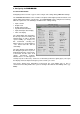
Buffer Size:
The setting ‘Buffer Size’ determines the latency between incoming and outgoing data, as well
as affecting system stability (see chapter 13). We recommend selecting the highest value here
(8192 samples) - the board itself will still run comfortably.
SPDIF In:
Defines the input for the SPDIF
signal. 'Coaxial' relates to the white
phono plug, 'Internal' to the jumper
CD In (ST3), 'ADAT1' to the optical
input ADAT1.
SPDIF Out:
The SPDIF output signal is
constantly available at the internal
jumper Sync Out (ST4) and the red
phono plug. After selecting 'ADAT1' it
is also routed to the optical output
ADAT1. For further details about the
settings ‘Professional’, ‘Emphasis’
and ‘Non-Audio’, please refer to
chapter 11.
Clock Mode:
The card can be configured to use
the external input signal (AutoSync)
or its internal clock (Master) as clock
source.
Pref. Sync Ref.:
Used to pre-select the desired clock source. If the selected source isn't available the card will
change to the next available one. The currently used clock source and sample rate is displayed
in the SyncRef display.
Options:
'Alt. ASIO Mode' activates a different ASIO callback method. This setting is performed in real-
time and under operation. Therefore it's very easy to check whether this setting results in any
performance advantages. This setting is recommended for Logic (emagic) and Spark (TC).
After activating 'ADAT1 Int.' the optical input ADAT1 will be routed to the internal input (CD In).
Then the 4- or 8-channel signal of an AEB-I can be received. The optical input can no longer be
used with an ADAT signal, but can still be used as SPDIF input. For this to work select 'ADAT1'
under 'SPDIF In'.