User's Guide SyncAlign ® ® SyncCheck Intelligent Clock Control TM Hi-Precision 24 Bit / 96 kHz 8 Channel AD / DA-Converter ADAT® optical / TDIF®-1 Interface Digital 24 Bit Interface / Format Converter TDIF-1 24 Bit Interface
User's Guide ADI-8 DS © RME
Contents 1 2 3 4 Introduction............................................................ 4 Supplied Contents ................................................. 4 Brief Description and Characteristics ................... 4 Technical Specifications ....................................... 5 4.1 Analog Specs ...................................................... 5 4.2 Digital Specs ....................................................... 5 5 First Usage - Quick Start........................................
1. Introduction Congratulations on your purchase of a ADI-8 DS. This hi-quality analog to digital and digital to analog converter includes ADAT optical and TDIF-1 digital interfaces. It precisely converts analog audio data into a digital data stream and into the format of your choice. Newest circuit technology combined with latest integrated circuits result in a unique and outstanding device, meeting highest quality standards. The ADI-8 DS will excite you even after many years of operation. 2.
4. Technical Specifications • Power supply: Internal, 100-240 V AC, 30 Watts • Dimensions 483 x 44 x 205 mm • Weight: 2 kg 4.1 Analog Specs AD • Resolution AD: 24 bit • Signal to Noise ratio: 113 dB RMS unweighted, 117 dBA • THD: < -110 dB, < 0.00032 % • THD+N: < -104 dB, < 0.00063 % • Crosstalk: > 130 dB • Maximum input level AD: +19 dBu • Frequency response AD, -0.1 dB: 5 Hz – 21.
5. First Usage - Quick Start The clearly structured front panel design ensures an easy start when working with the device for the first time. Nevertheless we recommend to study at least the chapters 'Clock Section' and 'Copy Mode', as the extensive usage of format converter and clock options may result in some behaviour that may require further explanation. We therefore recommend to carefully study chapter 7 (Clock section) and 8.3 (Copy Mode).
6. Inputs and Outputs 6.1 Analog Inputs The ADI-8 DS back provides 8 (stereo) 1/4" TRS jacks and a 25 pin D-sub jack. Both are internally connected, so not operational at the same time. The electronic input stage is built in a servo balanced design which handles monaural and stereo jacks correctly. When used unbalanced it automatically corrects the gain by 6 dB. When using unbalanced cables with XLR jacks pin 3 of the cable's jack should be connected to pin 1 (ground).
6.2 Analog Outputs The 8 short circuit protected, low impedance and servo balanced line outputs are available as (stereo) 1/4" TRS jacks and 25 pin D-sub jack. Both are internally connected, and - in contrary to the inputs - can be used simultaneously. The electronic output stage is built in a servo balanced design which handles monaural and stereo jacks correctly. When used unbalanced it automatically corrects the gain by 6 dB.
6.3 Digital Inputs The ADI-8 DS provides two digital inputs, both in ADAT optical and TDIF-1 format. In normal operation only the MAIN inputs are used. When using more than the first 4 channels at activated COMBINE BS (Bit Split) or DS (Double Speed), the AUX inputs also have to be used. The key DIGITAL INPUT sets the desired input active. The ADAT optical inputs of the ADI-8 DS are fully compatible with all ADAT optical outputs.
6.4 Digital Outputs The ADI-8 DS provides two digital outputs, both in ADAT optical and TDIF-1 format. In normal operation only the MAIN outputs are used. When using more than the first 4 channels at activated PROCESS BS or DS, the AUX outputs also have to be used. TDIF and ADAT optical outputs always operate simultaneously and carry the same audio data. As long as PROCESS BS or DS isn't activated MAIN and AUX also operate simultaneously and carry the same audio data.
6.5 Word Clock Input and Output Input The ADI-8 DS' word clock input is active, when EXT is chosen in the clock section (see chapter 7, Clock Section). As soon as a valid signal is detected, the EXT LED is constantly lit, otherwise it is flashing slowly. Thanks to RME's Signal Adaptation Circuit, the word clock input still works correctly even with heavily mis-shaped, dc-prone, too small or overshoot-prone signals. Thanks to automatic signal centering, 300 mV (0.3V) input level are sufficient in principle.
7. Clock Section The ADI-8 DS provides an outstanding clock section with professional features you won't find anywhere else. The unique Intelligent Clock Control (ICC) enables a flexible operation with internal clock (44.1 and 48 kHz, in DS mode 88.2 and 96 kHz), external word clock or the digital input signals. These options are easy to understand and easy to use thanks to a clear display of the corresponding lock and sync state.
8. Word Clock 8.1 Operation and Technical Background In the analogue domain one can connect any device to another device, a synchronization is not necessary. Digital audio is different. Correct interpretation of digital audio data is dependent upon a definite sample frequency. Signals can only be correctly processed or transferred between devices if these all share the same clock. Otherwise digital signals are misinterpreted, causing distortion, clicks/crackle and even dropouts.
The TDIF format is especially critical with respect to word clock. We have mentioned this in different places of this manual: When the ADI-8 DD is slave no additional word clock connection is necessary. In case DA88 and/or DA38 are slave the word clock output of the ADI-8 DD has to be connected to the word clock input of the first (master) recorder. When using more than one recorder a special sync cable (Tascam part number PW-88S) is needed.
9. Special Functions 9.1 Bit Split Especially digital tape recorders are often limited to 16 bit resolution. To use the complete dynamic range of the ADI-8 DS with such devices the functions BIT SPLIT and COMBINE were integrated. This technique is a simple but effective solution, differently used by several manufacturers. The method used in the ADI-8 DS is compatible to the one used by Yamaha in their digital mixing desk 02R, so the ADI-8 DS can be used directly in 24 bit operation with this desk.
9.3 Copy Mode The function COPY MODE turns the ADI-8 DS into an outstanding ADAT to TDIF and TDIF to ADAT format converter, a digital patchbay, a signal distributor and a digital 16/24 bit converter. When COPY MODE is active the digital input signal of the DA-converter is routed directly to the digital outputs of the AD-converter. The AD-converter can't be used anymore. That's why the complete AD clock section will also be disabled. All LEDs of the AD-section (INPUT LEVEL, OK, OVR, INPUT, EXT., INT.
9.4 Dither Thanks to BIT SPLIT and COMBINE the ADI-8 DS preserves full 24 bit resolution even when working with 16 bit devices. It may happen that the actual recording situation does not allow a usage of BIT SPLIT/COMBINE. When using Double Speed (88.2 and 96 kHz) BIT SPLIT/COMBINE is not available. When transferring to a 16-bit medium, the word length is reduced by discarding the lower bits. This truncation causes distortion at the low-level components of the signal.
9.5 DS - Double Speed When activating the Double Speed mode the ADI-8 DS operates at double sample rate. The internal clock 44.1 kHz turns to 88.2 kHz, 48 kHz to 96 kHz. With this the device is able to process even ultra-sound above 40 kHz at its analog inputs and outputs. AD/DA-converter and COPY mode still use full 24 bit resolution. The ADAT optical interface does not support sample rates above 48 kHz. Therefore the converter uses a Sample Split method, which operates similar to the BIT SPLIT function.
10. Controls and Connectors Front AD-Converter Select Input Level +4 dBu, -10 dBV Lo Gain Clock Section Level Indication OK = -40 dBFS OVR= Overload Clock Section AD and DA INPUT= Digital input signal EXT.= Word clock signal INT.= Crystal 44.
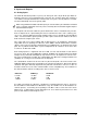
11. Connector Pinouts D-Sub analog input / output The 25 pin D-sub connectors of analog input and output are wired as shown in this table: Channel D-sub 1+ 24 112 2+ 10 223 3+ 21 39 4+ 7 420 5+ 18 56 6+ 4 617 7+ 15 73 8+ 1 814 GND is connected to pins 2, 5, 8, 11, 16, 19, 22, 25. Pin 13 is unconnected. D-Sub TDIF-1 The 25 pin D-sub connectors are wired according to TDIF-1, version 1.
12.
13. Warranty Before shipping each ADI-8 DS is tested by RME in a complete test sequence. Using only the best hi-grade components allows us to offer two years of warranty. The copy of the sales receipt or the Bill of Sale is your warranty legitimation. In case of any error or defect please contact your local dealer. The warranty does not cover damage due to abuse, incorrect installation or incorrect handling.
CE This device has been tested and found to comply with the limits of the European Council Directive on the approximation of the laws of the member states relating to electromagnetic compatibility (EMVG) according to EN 55022 class B and EN50082-1. FCC Compliance Statement Certified to comply with the limits for a Class B computing device according to subpart J or part 15 of FCC rules. See instructions if interference to radio reception is suspected.