
User`s guide


User's Guide ADI-8 DS © RME
15
9. Special Functions
9.1 Bit Split
Especially digital tape recorders are often limited to 16 bit resolution. To use the complete dy-
namic range of the ADI-8 DS with such devices the functions BIT SPLIT and COMBINE
were integrated. This technique is a simple but effective solution, differently used by several
manufacturers.
The method used in the ADI-8 DS is compatible to the one used by Yamaha in their digital
mixing desk 02R, so the ADI-8 DS can be used directly in 24 bit operation with this desk.
Additional the COPY MODE (see chapter 8.2 Copy Mode) allows an operation of BIT SPLIT
and COMBINE in digital domain. This allows to use the ADAT inputs of the 02R with full 24 bit
resolution (normally limited to 20 bit).
BIT SPLIT divides the 24 bit signal into a 16 bit and an 8 bit signal. When recording on 16 bit
machines two tracks are required for each channel, an 8 track machine will record 4 channels.
To transmit all 8 channels of the ADI-8 DS two digital interfaces (16 tracks) are provided
and have to be used.
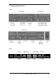
On the back of the ADI-8 DS two ports of each TDIF and ADAT format named MAIN and
AUX can be found.
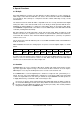
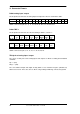
With PROCESS BS active the analog inputs are processed to the digital outputs as shown
below:
Input 1 2 3 4 5 6 7 8
Output
Port
1/5
MAIN
2/6
MAIN
3/7
MAIN
4/8
MAIN
1/5
AUX
2/6
AUX
3/7
AUX
4/8
AUX
As long as not more than the first 4 channels are used only the MAIN output is necessary. It
makes no sense to connect AUX as it carries no data. When using inputs 5-8 the AUX output
also has to be used and carries the data of inputs 5-8.
9.2 Combine
COMBINE BS is the reverse function of BIT SPLIT, putting split signals back together accord-
ing to the upper table. Again: As long as not more than the first 4 channels are used only the
MAIN input is necessary. The AUX input has to be used to receive channels 5-8.
As COMBINE BS is fed from digital inputs a function to verify lock and synchronisity is re-
quired. The lock state of the MAIN input is indicated as usual by the LEDs of the Clock D/A
section. The input AUX has its own lock/sync LED at the key COMBINE. This LED operates in
a slightly different way, as it indicates both Lock and Sync state.
As long as no signal is found at the AUX input the SYNC LED will be off. When a valid sig-
nal is fed the LED begins to flash (lock state). When the data received is synchronous to
the data at the input MAIN the LED will stay lit (lock+sync state). This securely indicates
and prevents audio errors in COMBINE mode.