
User`s guide


20
User's Guide ADI-8 DS © RME
11. Connector Pinouts
D-Sub analog input / output
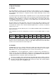
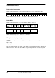
The 25 pin D-sub connectors of analog input and output are wired as shown in this table:
Channel
1+ 1- 2+ 2- 3+ 3- 4+ 4- 5+ 5- 6+ 6- 7+ 7- 8+ 8-
D-sub 24 12 10 23 21 9 7 20 18 6 4 17 15 3 1 14
GND is connected to pins 2, 5, 8, 11, 16, 19, 22, 25. Pin 13 is unconnected.
D-Sub TDIF-1
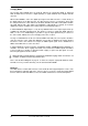
The 25 pin D-sub connectors are wired according to TDIF-1, version 1.1:
Signal
Out
1/2
Out
3/4
Out
5/6
Out
7/8
Out
LRCK
Out
EMPH
Out
FS0
Out
FS1
D-sub
1 2 3 4 5 18 6 19
Signal
In
FS1
In
FS0
In
EMPH
In
LRCK
In
7/8
In
5/6
In
3/4
In
1/2
D-sub
20 8 21 9 10 11 12 13
GND is connected to pins 7, 14, 15, 16, 17, 22, 23, 24, 25.
TRS-jacks of analog input / output
The stereo ¼" TRS jacks of the analog inputs and outputs are wired according to international
standards:
Tip = + (hot)
Ring = – (cold)
The servo balanced input and output circuitry allows to use monaural TS jacks (unbalanced)
with no loss in level. This is the same as when using a TRS-jack with ring connected to ground.