
User`s guide


User's Guide HDSP MADI © RME
37
The actual end of these problems is offered by the SteadyClock technology of the HDSP
MADI. Combining the advantages of modern and fastest digital technology with analog filter
techniques, re-gaining a low jitter clock signal of 22 MHz from a slow word clock of 44.1 kHz is
no problem anymore. Additionally, jitter on the input signal is highly rejected, so that even in real
world usage the re-gained clock signal is of highest quality.
This is especially true when extracting the word clock out of a MADI signal. Caused by the
MADI format itself, such a signal will have around 80 ns of jitter, which is reduced to about 1 ns
by SteadyClock.
24.3 Cabling and Termination
Word clock signals are usually distributed in the form of a network, split with BNC T-adapters
and terminated with resistors. We recommend using off-the-shelf BNC cables to connect all
devices, as this type of cable is used for most computer networks. You will find all the neces-
sary components (T-adapters, terminators, cables) in most electronics and/or computer stores.
The latter usually carries 50 Ohms components. The 75 Ohms components used for word clock
are part of video technology (RG59).
Ideally, the word clock signal is a 5 Volt square wave with the frequency of the sample rate, of
which the harmonics go up to far above 500 kHz. To avoid voltage loss and reflections, both the
cable itself and the terminating resistor at the end of the chain should have an impedance of 75
Ohm. If the voltage is too low, synchronization will fail. High frequency reflection effects can
cause both jitter and sync failure.
Unfortunately there are still many devices on the market, even newer digital mixing consoles,
which are supplied with a word clock output that can only be called unsatisfactory. If the output
breaks down to 3 Volts when terminating with 75 Ohms, you have to take into account that a
device, of which the input only works from 2.8 Volts and above, does not function correctly al-
ready after 3 meter cable length. So it is not astonishing that because of the higher voltage,
word clock networks are in some cases more stable and reliable if cables are not terminated at
all.
Ideally all outputs of word clock delivering devices are designed with very low impedance, but
all word clock inputs as high impedance types, in order to not weaken the signal on the chain.
But there are also negative examples, when the 75 Ohms are built into the device and cannot
be switched off. In this case the network load is often 2 x 75 Ohms, and the user is forced to
buy a special word clock distributor. Note that such a device is generally recommended for big-
ger studios.
The HDSP MADI's word clock input can be high-impedance or terminated internally, ensuring
maximum flexibility. If termination is necessary (e.g. because the card is the last device in the
chain), activate the switch TERM between the BNC jacks on the Expansion Board so that the
yellow TERM LED lights up (see chapter 24.1).
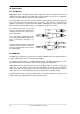
In case the HDSP MADI resides within a chain of devices receiving word clock, plug a T-
adapter into its BNC input jack, and the cable supplying the word clock signal to one end of the
adapter. Connect the free end to the next device in the chain via a further BNC cable. The last
device in the chain should be terminated using another T-adapter and a 75 Ohm resistor (avail-
able as short BNC plug). Of course devices with internal termination do not need T-adaptor and
terminator plug.
Due to the outstanding SteadyClock technology of the HDSP MADI, we recommend not to
pass the input signal via T-adapter, but to use the card's word clock output instead. Thanks
to SteadyClock, the input signal will both be freed from jitter and - in case of loss or drop out
– be reset to a valid frequency.