User’s Guide MADI Router 12 x 12 Port MADI Stream Switcher/Router/Merger With Integrated 768 x 256 Channel Routing Matrix 4 Coaxial Inputs and Outputs 4 Optical Inputs and Outputs 4 Twisted Pair Inputs and Outputs Preset Memory TFT Display Word Clock I/O 24 Bit / 192 kHz Digital Audio Firmware 1.
User’s Guide MADI Router © RME
Table of Contents Important Safety Instructions ...................................... 4 1. Introduction ............................................................... 5 2. Package Contents ..................................................... 5 3. Brief Description and Characteristics ..................... 5 4. Firmware .................................................................... 6 5. Technical Specifications .......................................... 7 5.1 Inputs .................................
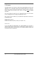
Important Safety Instructions ATTENTION! Do not open chassis – risk of electric shock The unit has non-isolated live parts inside. No user serviceable parts inside. Refer service to qualified service personnel. Mains • The device must be earthed – never use it without proper grounding • Do not use defective power cords • Operation of the device is limited to the manual • Use same type of fuse only To reduce the risk of fire or electric shock do not expose this device to rain or moisture.
1. Introduction The RME MADI Router is designed to be the centerpiece of small and large digital audio networks based on the widely adopted point-to-point Multichannel Audio Digital Interface (MADI alias AES10). It is able to manage all the tasks that are required to set up and to control a MADI environment, from inspection of signal integrity and sampling frequency, to format conversion, to full stream and single-channel block routing.
4. Firmware The MADI Router’s core has been created using programmable logic and is user updateable. This is achieved by simply saving a firmware update file to a USB stick, attaching the USB stick directly to the MADI Router’s USB port and then running the firmware update from the SETUP menu. Please see chapter 7.5.6 for detailed information. At the time of writing this manual, the unit is shipped with firmware 1.29. The firmware version is displayed on the TFT display after powering the unit on.
5. Technical Specifications ● ● ● ● ● Two internal redundant power supplies, 100-240V AC, typ. 30W, max. 75W1 Dimensions without rack ears (WxHxD): 440 x 44 x 240 mm (17.32” x 1.73” x 9.45”) Temperature range: +5° up to +50° Celsius (41° F up to 122° F) Relative humidity: < 75%, non condensing Weight: 2.8 kg 5.1 Inputs MADI ● ● Coaxial via BNC, 75 Ohm, according to AES10-1991 High-sensitivity input stage (< 0.2 Vpp) ● ● Optical via FDDI duplex SC connector 62.
5.2 Outputs MADI ● ● ● Coaxial via BNC, 75 Ohm, according2 to AES10-1991 Output voltage 1,6 Vpp Cable length: up to 200 m ● ● ● Optical via FDDI duplex SC connector 62.5/125 and 50/125 multimode compatible Fiber length: up to 2000m ● ● ● Twisted Pair via RJ45 “EXT” connector (combined input and output) Category 5e cable: length up to 75m Category 7 cable: length up to 150m Word Clock ● ● ● ● ● BNC Max. output voltage: 3,3 Vpp Output voltage @ 75 Ohm: 1.
6. First Usage 6.1 Overview & Basic Concepts Connect a power cable to either of the MADI Router's AC inlets and flip the adjacent power switch. The device will go into Standby or Power On mode, depending on the state that the device was in when the rear switch was last turned off. This is indicated by the color of the illuminated Standby switch on the front of the device - red for standby, white for power on.
● The [ROUTE] button opens the main routing page from which all MADI signals can be routed in streams, individual channels, or in groups of 2, 4 or 8 channels. ● The concept of the patching operation is to address an output first. Selecting an output is non-destructive and will not alter the current routing. It should always be the first step when creating a patch. Conversely, adjusting the input selector is destructive and changes the routing immediately.
6.3 Loading a Preset From a USB Flash Drive If you have been provided with a configuration file ROUTING.RME, save it onto a USB flash drive (do not place it into a folder), then eject the USB Stick from the computer and connect it to the USB port on the MADI Router. 1. 2. 3. 4. Press [PRESET] Rotate the [IN] encoder to select “Load USB Preset” Press the [IN] encoder Confirm that you want to load the preset by pressing [IN] again The preset is now loaded and activated.
7. Front Panel Operation and Usage The TFT display provides quick access to the status and control options of the MADI Router. The device’s features are controlled with a set of four buttons and two rotary encoders that can also be pushed as buttons. The buttons are labeled and in this manual referred to as [ROUTE], [GANG], [PRESET], [SETUP], [IN] and [OUT]. 7.
7.2 Detailed Input Status While in the status display, rotating or pushing the [IN] encoder immediately activates the 'Inspect Input' screen. This page shows the detailed status of an input port selected by turning the [IN] encoder. Information about all other ports including routing is hidden in order to allow a dedicated focus on the selected input port. Pressing either encoder exits the detailed view and returns to the main status display.
● S/MUX: ? | Off Double Speed (88.2/96kHz) and Quad Speed (176/192kHz) signals that make use of the sample multiplexing method instead of longer frame lengths cannot be identified automatically, but are instead shown as Single Speed signals. In this case, S/MUX shows “?” to indicate that the incoming signal may or may not be multiplexed. If a 96k frame is detected, this field shows “Off”. Note: the MADI Router does not perform sample rate conversion.
7.3 ROUTE Menu The [ROUTE] button opens the routing menu. It is used to create routings by first selecting an output stream with the [OUT] encoder and then assigning a MADI signal to it from any of the twelve physical input ports (full stream routing) or the four matrices (channel block or individual channel routing) by turning the [IN] encoder. Full Stream Routing Full Stream Routing describes a fully transparent MADI connection between an input and at least one output port.
To delete a routing, rotate the input encoder counter-clockwise until the cursor disappears to the left of the "A Optical" input icon, or rotate the [IN] encoder counterclockwise while pressing the [GANG] button. To copy a routing to the next port on the right of the currently selected output port, press and hold the [GANG] button while turning the [OUT] encoder clockwise.
Channel Block and Individual Channel Routing Channel Routing describes the process of creating new MADI streams with the help of four 768x64 audio channel matrices (at 44.1/48kHz sampling rate) that are referred to on the display as “MX 1” to “MX 4”. These matrices can be routed to any of the twelve physical outputs using the same process that is described above – the four matrices extend the 12 physical input ports by four “composed streams”.
icons. The four matrices appear once the cursor passes the last physical input icon („D Twisted Pair“): Note that in order to edit a matrix, it has to be routed to at least one physical output port. If the same matrix is routed to several output ports, it can be accessed from all outputs that it is sent to, using this procedure. 5.
7.3.2 Inspecting a matrix In order to inspect a matrix, follow the steps above to access the matrix first. 1. The matrix is displayed as a horizontal bar in the middle of the display. The bottom row shows a blue cursor that moves along the matrix outputs when the [OUT] encoder is rotated. Only one patch is shown at a time. To get an overview of all the patches, use the [OUT] encoder to browse through all output channels.
7.3.3 Routing Indicator A thin line in the lower half of the display reflects the current fragmentation of the output patches. It serves as an aid to get a quick overview of what is happening across the complete matrix. It has the same length as the channel indicator (here shown for 64 channels).
Example 1: Uninterrupted thick line A thick line states that for the duration of the line, the patches are continuously following the +1:+1 principle: Input 1 Input 2 Input 3 Input 4 ... Input 64 Output 64 ... Output 4 Output 3 Output 2 Output 1 Note that the input and output channel number do not have to be identical. Routings may also include an offset, for example: Input 5 Input 6 Input 7 Input 8 ... Input 39 Output 35 ...
Example 2, 3: Interrupted thick line An interruption in the thick line states that the consecutive input channel increments are interrupted. A thick line that is interrupted once between channel 32 and 33, as shown in example 2, would for instance be the result of the following two routings: Input 1 Input .. Input 32 Input 33 ... Input 34 Output 64 ... Output 33 Output 32 Output .. Output 1 Input 1 Input .. Input 32 Input 33 ... Input 34 Output 64 ... Output 33 Output 32 Output ..
Example 4: Uninterrupted thin line Thin lines reflect the so-called 1:n state. This means that for the duration of the thin line, each output channel receives its signal from the exact same input channel. Input 1 Input 2 Input 3 Input 4 ... Input 64 Output 64 ... Output 4 Output 3 Output 2 Output 1 Example 5, 6: Interrupted thin line Interruptions in the thin line simply show a break in the 1:n process, such as: Input 2 Input 4 Output 64 ... Output 33 Output 32 ...
7.3.4 Modifying a matrix In order to modify a matrix, follow the steps outlined in chapter 7.3.1 to first access the matrix. Then move the blue cursor to the output channels for which you'd like to choose a different input source. 1. Rotate the [IN] encoder in order to immediately change the current set of source channels. In the above example, rotating it clockwise by one step would move the grey cursor to channels 25-32, while the output cursor remains on channels 1-8 of Matrix 1. 2.
This feature toggles the type of patch from consecutive input channels to ‘one to many’, in the routing indicator shown as a thin line. In case the patch had been deleted, [GANG] + push [INPUT] creates a new patch. [GANG] + rotate encoder counter-clockwise Rotating either encoder counter-clockwise while pushing the [GANG] button deletes the patches. Note that there always has to be a patch to output channel one since the matrix uses it as a clock reference when in Auto-Sync mode.
7.4 PRESET Menu In addition to saving its current state, the MADI Router has sufficient memory for 15 internal presets that can be previewed, recalled, cleared and saved. Furthermore a routing file from an external USB stick can be loaded into its current state and from there saved to any of the internal presets. A preset contains all clocking and transparency settings along with the routing.
7.5 SETUP Menu The setup menu gives access to the individual clock settings for each matrix, the wordclock output settings and also allows the user to update the firmware of the device. It can be accessed by pressing the [SETUP] button while the unit displays its IDLE screen. 7.5.1 Matrix Clocking The Matrix Clocking section of the setup menu is used to set the correct reference clock and sample rate settings for each of the four internal matrices and to create one additional default setting.
Source: Default uses the clock source defined in the default screen Internal uses the MADI Router’s internal reference clock Auto Sync uses the clock of the audio channel routed to the first output channel of the matrix Word Clock uses a reference clock from the physical word clock input Optical A, Optical B, Optical C, Optical D Coaxial A, Coaxial B, Coaxial C, Coaxial D Twisted A, Twisted B, Twisted C, Twisted D synchronizes the matrix to a valid MADI signal detected at the selected physical input.
S/MUX: Values: On | Off “Sample multiplexing” (S/MUX) describes the technique of spreading the larger amount of samples per audio channel in double speed (88.2, 96kHz) and quad speed (176.4, 192kHz) signals to the 56 or 64 channels of a single speed MADI signal.
7.5.2 Word Clock Output The word clock output menu can be used to set the clock at the physical output. Source: Values: Internal Auto Sync Word clock Optical A, Optical B, Optical C, Optical D Coaxial A, Coaxial B, Coaxial C, Coaxial D Twisted A, Twisted B, Twisted C, Twisted D Rate: If set to internal, a sampling rate can be set with this second menu item to the following rates (Hz): 32k 44.1k 48k 88.2k 96k 176.
7.5.3 Bit Transparency The Bit Transparency menu gives access to two settings that are related to the MADI streams and to the matrices. The [OUT] encoder is used to access the two settings, the [IN] encoder is used to change their value. A short text informs about the current setting. Stream Routing Options: Activate MADI receiver Before routed to the selected output port, bit stream is recovered and decoded. Content of MADI is left untouched.
Pass MADI subframes All bits of a subframe are passed to the output transparently (including proprietary bit assignments). This setting is necessary when control data – for example to control a microphone preamp – is present and should be passed on. However, since individual channels may contain additional information such as the the grouping of channels and their channel numbers, there may be problems if the receiving MADI device decodes this information.
7.5.6 Firmware Updates “Firmware Updates” allows users to update the device firmware. In order to perform an update, a firmware file (main.upd) has to be placed in the root folder of a USB stick and the stick attached to the rear USB port of the device. After an initial confirmation, the device first checks for a firmware update file on the attached USB stick, then compares it to the currently flashed firmware.
8. Appendix RME news and further information can be found on our website: http://www.rme-audio.com Worldwide Distributor and manufacturer’s representative: Audio AG Am Pfanderling 60 D-85778 Haimhausen Germany Tel.: (+49) 8133 / 918170 Fax: (+49) 8133 / 9166 E-Mail: info@audioag.com Trademarks All trademarks and registered trademarks belong to their respective owners. S/MUX is copyright Sonorus. Copyright © RME, 5/2014. Version 1.
9. Declarations of Conformity CE The RME MADI Router conforms with the essential emission requirements of the European Generic Emission Standard EN 61000-6-3:2007 + A1:2011 and the immunity requirements according to the European Generic Immunity Standard EN 61000-62:2005 and therefore complies with the essential requirements and provisions of the EMC directive. FCC This device complies with Part 15 of the FCC Rules.
RoHS This product has been soldered lead-free and fulfils the requirements of the RoHS directive. Note on disposal According to the guideline RL2002/96/EG (WEEE – Directive on Waste Electrical and Electronic Equipment), valid for all European countries, this product has to be recycled at the end of its lifetime. In case a disposal of electronic waste is not possible, the recycling can also be done by Audio AG, the distributor of the MADI Router.