
User`s guide

12
User’s Guide OctaMic II © RME
7. Front Panel Controls
7.1 Displays
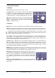
+48V (LED) lights up when phantom power is active.
The CLIP LED has been designed to act like the OVR LEDs of
the ADI-8 series. It lights up 2 dB before the chosen reference
level plus a headroom of 9 dB. At Hi Gain the LED lights up at
+17 dBu output level, selecting +4 dBu it lights up at +11 dBu.
SIG (Signal) indicates the presence of an input signal. The
LED has a detection range of more than 50 dB using multiple
brightness states. With this, SIG acts as useful level control,
helping to set GAIN correctly.
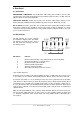
7.2 Controls
GAIN allows for a step-less adjustment of the amplification between +6 dB and +60 dB.
+48V (switch) activates phantom power. Phantom power should only be activated when using
condensor microphones which require such a power supply, and only on the specific channel.
Connecting and disconnecting microphones while phantom power is active causes a high
voltage surge, which can destroy the microphone input stage! Switch phantom power off
before connecting/disconnecting any external device.
The OctaMic II turns on the phantom power smoothly during one second, from 0 to 48 Volts.
This technique is advantageous for the connected microphone as well as the OctaMic II. The
phantom power of the OctaMic II is short-circuit proof. With a maximum load on all eight chan-
nels the internal voltage does not drop below 47 Volts.
LO CUT activates a high-pass (bass removal) with 18 dB per octave, at a cut-off-frequency of
80 Hz. This filter can remove rumble, subsonic-noise and other low frequency noises. The LO
CUT of the OctaMic II shows a slow roll-off in the frequency response, without any resonance
rise, and provides low THD figures. At a low 20 Hz, where the fundamental signal is already
attenuated by 34 dB, the distortion is around 0.13 %.
PHASE changes the polarity (180°). Phase cancellations and sound changes can be caused by
using multiple microphones at different places, or wrongly soldered cables. In such cases
PHASE can eliminate the error by adding an additional phase inversion.
Clip Hold is activated by pressing the key for two seconds. As soon
as an overload is detected, the corresponding Clip LED begins to
flash once per second. With this, a momentary overload stays visible
for a longer time. Pressing the key once resets the Clip display.
Pressing the key again for two seconds deactivates the Clip Hold
mode.
Hi Gain / +4 dBu / -10 dBV: Defines the reference level of the Line
Level Outputs, equalling a full scale level of the AD-converters. See
chapter 10.2.