
User Manual


User's Guide HDSP AES-32 © RME
7
5. Hardware Installation
Before installing the PCI card, please make sure the computer is switched off and the
power cable is disconnected from the mains supply. Inserting or removing the card while
the computer is in operation can cause irreparable damage to both motherboard and card!
1. Disconnect the power cord and all other cables from the computer.
2. Remove the computer's housing. Further information on how to do this can be obtained from
your computer's instruction manual.
3. Important: Before removing the HDSP AES-32 from its protective bag, discharge any static
in your body by touching the metal chassis of the PC.
4. Prior to installation: Connect the HDSP AES-32 card to the Expansion Board using the sup-
plied flat ribbon cable.
5. Insert the HDSP AES-32 firmly into a free PCI slot, press and fasten the screw.
6. Insert the Expansion Board and fasten the screw.
7. Replace the computer's housing.
8. Reconnect all cables including the power cord.
6. Hardware - Connectors
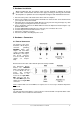
6.1 External Connectors
The bracket of the main
board has a D-sub 25 pin
connector providing
AES/EBU inputs and
outputs 1-4, and BNC
sockets providing word
clock input and output.
The D-sub connector
uses the Tascam pinout
(details see chapter
30.8).
Breakout and connection cables with this pinout are widely available.
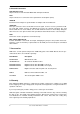
The Expansion Board's
bracket has AES/EBU
inputs and outputs 5-8 via
a second D-sub 25 con-
nector. The included
breakout cable is con-
nected to the 9-pin Mini-
DIN connector and pro-
vides two MIDI inputs and
outputs via four 5-pin DIN
connectors.
Note
: If neither AES I/O 5-8 nor MIDI I/O is required, it is not necessary to install the Expansion
Board at all.
Optional TCO
The optional Time Code Option is connected to the main board with a 10-pin flat ribbon cable.
Further details can be found in the TCO manual.