User's Guide MADI Converter 6 x Bidirectional MADI Optical to BNC Converter 6 coaxial Inputs and Outputs 6 optical Inputs and Outputs 1 to 3 MIDI Distributor
Contents Important Safety Instructions ..................................3 1 2 3 4 5 6 7 8 9 10 11 2 Introduction ...............................................................4 Package Contents .....................................................4 Technical Specifications ..........................................4 3.1 Inputs......................................................................4 3.2 Outputs...................................................................5 Operation ..............
Important Safety Instructions ATTENTION! Do not open chassis – risk of electric shock The unit has non-isolated live parts inside. No user serviceable parts inside. Refer service to qualified service personnel. Mains • The device must be earthed – never use it without proper grounding • Do not use defective power cords • Operation of the device is limited to the manual • Use same type of fuse only To reduce the risk of fire or electric shock do not expose this device to rain or moisture.
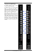
1. Introduction The MADI Converter is a useful tool for any kind of MADI signal. The device converts MADI digital audio streams from optical format to coaxial and from coaxial to optical. The compact 19" device with 1 unit height contains six bi-directional converters, operating fully independently. All 12 inputs are equipped with status LEDs on the front panel. All input signals will pass through absolutely unaltered.
MIDI • 1 x 16 channels MIDI • 5-pin DIN jack • Opto-coupled, ground free input • Fixed MIDI Thru functionality 3.3 Outputs MADI • Coaxial via BNC, 75 Ohm, according to AES10-1991 • Output voltage > 400 mVpp • Cable length: more than 100 m • Optical via FDDI duplex SC connector • 62.5/125 and 50/125 compatible • Fiber length: up to 2,000 m MIDI • 3 x 16 channels MIDI • 5-pin DIN jacks 4.
5. Operation with MADI Bridge The MADI converter is also an companion to RME's MADI Bridge. ideal The MADI Converter can convert the MADI Bridge's six coaxial inputs and outputs to optical, a format which is advantageous in live and installed setups, and for longer cable lengths. So in this combination, the MADI Bridge effectively offers eight optical I/Os. MADI Bridge and MADI Converter are perfectly designed for each other.
6. Inputs and Outputs 6.1 MADI Inputs The rear of the MADI Converter has six coaxial MADI inputs, available as BNC sockets. The sockets are ground-free and separated from ground by capacitive coupling. This method prevents ground loops and other distortions by potential differences between the connected units. Note that the transmission at the receiver still operates unbalanced. The BNC input's ground-free design is built according to AES10-1991. The input's impedance is 75 Ohm.
7. Technical Background 7.1 MADI Basics MADI, the serial Multichannel Audio Digital Interface, has been defined already in 1989 as an extension of the existing AES3 standard following several manufacturers' wish. The format also known as AES/EBU, a balanced bi-phase signal, is limited to two channels. Simply put, MADI contains 28 of those AES/EBU signals in serial, i. e. after one another, and the sample rate can still even vary by +/-12.5%. The limit which cannot be exceeded is a data rate of 100 Mbit/s.
7.2 MADI Converter Technology A MADI patchbay basically can be realized in two ways: using a complete signal regeneration (including reclocking), or by a buffered distribution of the un-processed input signal. Complete Signal Regeneration: This method requires a complete MADI receiver per input, and a complete MADI transmitter per output. The signal must be processed and reclocked. The costs are extreme, as the special MADI chip (required 8 times!) is already very expensive.
8.
9. Warranty Each individual MADI Converter undergoes comprehensive quality control and a complete test at IMM before shipping. The usage of high grade components should guarantee a long and trouble-free operation of the unit. If you suspect that your product is faulty, please contact your local retailer. Audio AG grants a limited manufacturer warranty of 6 months from the day of invoice showing the date of sale. The length of the warranty period is different per country.
11. Declaration of Conformity CE This device has been tested and found to comply with the limits of the European Council Directive on the approximation of the laws of the member states relating to electromagnetic compatibility according to RL2004/108/EG, and European Low Voltage Directive RL2006/95/EG. FCC This equipment has been tested and found to comply with the limits for a Class B digital device, pursuant to Part 15 of the FCC Rules.