
Manual


User's Guide MADI Converter © RME
5
MIDI
• 1 x 16 channels MIDI
• 5-pin DIN jack
• Opto-coupled, ground free input
• Fixed MIDI Thru functionality
3.3 Outputs
MADI
• Coaxial via BNC, 75 Ohm, according to AES10-1991
• Output voltage > 400 mVpp
• Cable length: more than 100 m
• Optical via FDDI duplex SC connector
• 62.5/125 and 50/125 compatible
• Fiber length: up to 2,000 m
MIDI
• 3 x 16 channels MIDI
• 5-pin DIN jacks
4. Operation
The user interface of the MADI Converter is characterized by a clearly structured architecture
and an unambiguous labelling of the front and rear sides.
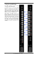
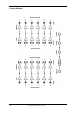
The status of the 12 inputs is displayed by dedicated LEDs on the front panel.
The rear of the MADI Converter hosts six coaxial BNC inputs and outputs, six optical inputs and
outputs, one MIDI input and 3 MIDI Thru outputs, all of them presented and labelled in a clear
and tidy way.
The specially developed internal high performance switching power supply allows operation of
the MADI converter with voltages ranging from 100 to 240 V AC. It is short-circuit-proof, has an
integrated line-filter, is fully regulated against voltage fluctuations, and suppresses mains inter-
ference.
Notes
• The INPUT LEDs of the MADI inputs are designed to light up with typical MADI signals. But
there is no real MADI detection and verification. Therefore, corrupt or non-standardized sig-
nals as well as high-frequency signals can cause the LEDs to turn on as well.
• The MIDI INPUT LED shows any MIDI activity, including MIDI Clock, MTC and Active Sens-
ing. The latter is sent by most keyboards every 0.3 seconds.