User Guide MADIface XT The world’s first and only USB 3 audio interface! ™ TotalMix FX ™ SyncAlign ™ SteadyClock ZLM ™ ™ SyncCheck USB 3 / USB 2.
General 1 2 3 4 5 Introduction ...............................................................8 Package Contents .....................................................8 System Requirements ..............................................8 Brief Description and Characteristics.....................8 First Usage – Quick Start 5.1 Connectors – Controls - Display ............................9 5.2 Quick Start ...........................................................
Usage and Operation 19 Front Panel Controls 19.1 Overviews ............................................................ 38 19.2 Encoders.............................................................. 38 19.3 Menu Keys MIC/GAIN and METERS .................. 39 19.4 Channel Menu...................................................... 39 19.5 Setup Menu.......................................................... 41 19.5.1 Options Menu............................................... 41 19.5.2 Setups Menu............
TotalMix FX 25 Routing and Monitoring 25.1 Overview ..............................................................58 25.2 The User Interface ...............................................60 25.3 The Channel.........................................................61 25.3.1 Settings ........................................................63 25.3.2 Equalizer ......................................................64 25.3.3 Dynamics .....................................................66 25.
Technical Reference 29 Technical Specifications 29.1 Analog.................................................................. 94 29.2 Digital Inputs ........................................................ 95 29.3 Digital Outputs ..................................................... 95 29.4 Digital ................................................................... 96 29.5 MIDI ..................................................................... 96 29.6 General ............................................
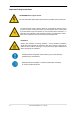
Important Safety Instructions ATTENTION! Do not open chassis No user serviceable parts inside. Refer service to qualified service personnel. To reduce the risk of fire or electric shock do not expose this device to rain or moisture. Prevent moisture and water from entering the device. Never leave a pot with liquid on top of the device. Do not use this product near water, i. e. swimming pool, bathtub or wet basement.
User's Guide MADIface XT General User's Guide MADIface XT © RME 7
1. Introduction Thank you for choosing the MADIface XT. This unique audio system is capable of transferring digital audio data directly into a computer, from any device equipped with a MADI interface. Analog sources can be connected to a stereo analog input, and 2 stereo analog outputs add full monitoring connectivity. Installation is simple, even for the inexperienced user, thanks to the latest Plug and Play technology.
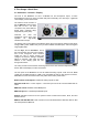
5. First Usage – Quick Start 5.1 Connectors – Controls – Display The front of the MADIface XT has 2 XLR/TRS line and microphone inputs, a stereo line/headphone output, two rotary encoders with push functionality, four menu keys, a graphical colour display, and six status LEDs. The Neutrik combo sockets of the two Mic/Line inputs provide XLR and 6.3 mm / 1/4" TRS connection. They have LEDs for Signal (SIG), Overload (Clip) and phantom power (48V).
USB 3.0. USB socket for connection to the computer. USB bus power is not supported. Compatible to USB 2.0. PCI Express. External PCI Express connector for Molex E-PCIe standard cables. POWER (switch): Turns the MADIface XT on and off. Socket for power connection. The locking type jack fits the locking type DC connector on the included power supply. After inserting the connector carefully turn it so that it locks. The included hi-performance switch mode power supply operates in the range of 100V to 240V AC.
User's Guide MADIface XT Driver Installation and Operation - Windows User's Guide MADIface XT © RME 11
6. Hardware, Driver and Firmware Installation 6.1 Driver Installation To simplify installation it is recommended to first install the drivers before the card is connected to the computer. But it will also work the other way round. Insert the RME Driver CD into your CD-ROM drive. The driver installer is located in the directory \HDSPe FX for external PCI Express \MADIface_USB for USB 3 and USB 2.0 Start rmeinstaller.exe and follow the instructions of the installer.
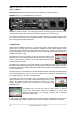
7. Configuring the MADIface XT 7.1 Settings Dialog – Main Tab Configuration of the MADIface XT is done via its own settings dialog.
Buffer Size The setting Buffer Size determines the latency between incoming and outgoing ASIO and WDM data, as well as affecting system stability (see chapter 9.1). While ASIO can use any offered buffer size, WDM is limited to 256 (XP) or 512 samples (Win 7/8). The driver handles this automatically, higher settings are only applied to ASIO while WDM will stay at 256/512 internally. Errors (USB only) does not refer to buffer errors, but USB transmission errors.
Options EQ+D for Record Switches EQ and Dynamics of all input channels into the recording path. In case Loopback has been activated the EQ and Dynamics of the Output channel are within the recording path. See also chapter 27.5. Word Clock In Term. Checking this option terminates the word input internally with 75 Ohms. TMS TMS activates the transmission of Channel Status data and Track Marker information from the AES and MADI input signal.
7.2 Option WDM Devices The WDM Devices configuration has one button to enter the edit dialog, a status display showing the number of currently enabled WDM devices, and a listbox to select between Stereo or Multi-Channel devices. The number represents both record and playback devices, so ‘1’ means one input and one output device. The screenshot to the right shows the stereo WDM devices available with the XT, and that only MADI 1/2 has been activated. Any number can be activated.
Changing to the tab Speaker presents a list of all currently activated WDM devices. Any of these can now get the Speaker property. Please note that defining more than one device as Speaker usually makes no sense, and the speakers also don’t get numbered or renamed in Windows, so it is impossible to find out which one is which. After leaving the dialog with OK the WDM devices are reloaded so Windows sees their new properties. You can now assign any surround mode, from stereo to 7.
7.3 Tab Global (PCI Express Mode) This tab includes several options that work on all currently installed cards. Lock Registry Default: off. Checking this option brings up a dialog to enter a password. Changes in the Settings dialog are no longer written to the registry. As the settings are always loaded from the registry when starting the computer, this method provides an easy way to define an initial state of the MADIface XT. Optimize Multi-Client Mixing Default: off.
7.4 Settings Dialog – Pitch (E-PCIe only) Usually soundcards and audio interfaces generate their internal clock (master mode) by a quartz. Therefore the internal clock can be set to 44.1 kHz or 48 kHz, but not to a value in between. SteadyClock, RME's sensational Low Jitter Clock System, is based on a Direct Digital Synthesizer (DDS). This superior circuitry can generate nearly any frequency with highest precision.
7.5 Clock Modes - Synchronisation In the digital world, all devices must be either Master (clock source) or Slave (clock receiver). Whenever several devices are linked within a system, there must always be a single master clock. A digital system can only have one master! If the card’s clock mode is set to 'Master', all other devices must be set to ‘Slave’. The MADIface XT utilizes a very user-friendly, intelligent clock control, called AutoSync.
8. Operation and Usage 8.1 Playback The MADIface XT can play back audio data in supported formats only (sample rate, bit resolution). Otherwise an error message appears (for example at 22 kHz and 8 bit). In the audio application being used, the XT must be selected as output device. This can often be found in the Options, Preferences or Settings menus under Playback Device, Audio Devices, Audio etc. We strongly recommend switching off all system sounds (via >Control Panel /Sounds<).
8.2 DVD-Playback (AC-3/DTS) AC-3 / DTS When using popular DVD software players like WinDVD and PowerDVD, their audio data stream can be sent to any AC-3/DTS capable receiver via the MADIface XT. For this to work an output wave device has to be selected in >Control Panel/ Sounds and Multimedia/ Audio< or >Control Panel/ Sound/Playback<. Also check 'use preferred device only'. The DVD software's audio properties now show the options 'SPDIF Out' or similar.
8.3 Multi-client Operation RME audio interfaces support multi-client operation. Several programs can be used at the same time. The formats ASIO and WDM can even be used on the same playback channels simultaneously. As WDM uses a real-time sample rate conversion (ASIO does not), all active ASIO software has to use the same sample rate. However, a better overview is maintained by using the channels exclusively.
9. Operation under ASIO 9.1 General Start the ASIO software and select ASIO HDSPe FX or ASIO MADIface USB as the audio I/O device. MADIface XT supports ASIO Direct Monitoring (ADM). Its MIDI I/Os can be used with both MME MIDI and DirectMusic MIDI. At a sample rate of 88.2 or 96 kHz (Double Speed mode), the number of channels available at the MADI input and output is halved. At a sample rate of 176.4 or 192 kHz (Quad Speed mode), the number of channels is reduced to 16.
10. Using multiple MADIface XT The current driver supports operation of up to three MADIface XT. All units have to be in sync, i.e. have to receive valid sync information either via word clock or by using AutoSync and feeding synchronized signals. • If one of the XTs is set to clock mode Master, all others have to be set to clock mode Slave, and have to be synced from the master, for example by feeding word clock. The clock modes of all units have to be set up correctly in their Settings dialogs.
12. Hotline – Troubleshooting The newest information can always be found on our website www.rme-audio.com, section FAQ, Latest Additions. The dialog 'New hardware component found’ does not appear: • Check whether the PCI Express interface is correctly inserted in the PCI Express slot. The card and drivers have been installed correctly, but playback does not work: • Check whether the MADIface XT appears in the Device Manager. When the device has a yellow exclamation mark, then there is a conflict.
User's Guide MADIface XT Driver Installation and Operation – Mac OS X User's Guide MADIface XT © RME 27
13. Driver and Flash Update 13.1 Driver Installation After the MADIface has been connected to the computer and switched on install the drivers from the RME Driver CD. The driver files are located in the folder \Fireface_USB for USB 3 and USB 2.0 \HDSPe FX for external PCI Express Installation works automatically by a double-click on the file Fireface_USB.pkg or hdspe_fx.pkg.
13.3 Firmware Update The Flash Update Tool updates the MADIface XT card to the latest firmware version. It requires an already installed driver. Start the program HDSPe FX Flash Update or RME USB Series Flash Tool. The Flash Update Tool displays the current revisions inside the XT, and whether it needs an update or not. If so, then simply press the 'Update' button. A progress bar will indicate when the flash process is finished. The bar moves slowly first (program), then faster (verify).
14. Configuring the MADIface XT 14.1 Settings Dialog Configuring the MADIface XT is done via its own settings dialog. The panel 'Settings' can be opened by clicking on the hammer or flame icon in the dock. The mixer of the MADIface XT, TotalMix FX, can be opened by clicking on the DSP FX icon in the dock. The MADIface hardware offers a number of helpful, well thought-of practical functions and options which affect how the card operates - it can be configured to suit many different requirements.
Options EQ+D for Record Switches EQ and Dynamics of all input channels into the recording path. In case Loopback has been activated the EQ and Dynamics of the Output channel are within the recording path. See also chapter 27.5. Word Clock In Term. Checking this option terminates the word clock input internally with 75 Ohms. Mirror MADI1 Output to MADI2 and 3 This option provides a quick and simple solution to mirror the first MADI output to outputs 2 and 3.
14.2 Clock Modes - Synchronisation In the digital world, all devices must be either Master (clock source) or Slave (clock receiver). Whenever several devices are linked within a system, there must always be a single master clock. A digital system can only have one master! If the card’s clock mode is set to 'Master', all other devices must be set to ‘Slave’. The MADIface XT utilizes a very user-friendly, intelligent clock control, called AutoSync.
15. Mac OS X FAQ 15.1 MIDI doesn't work In some cases the applications do not show the MIDI port. The reason for this is usually visible within the Audio MIDI Setup – MIDI Window. It displays no RME MIDI device, or the device is greyed out and therefore inactive. Mostly, removing the greyed out device and searching for MIDI devices again will solve the problem. The HDSPe MIDI driver is a plugin. During installation it will be copied to >Library/ Audio/ MIDI Drivers<. Its name is HDSPe FX MIDI.plugin.
16. Using multiple MADIface XT OS X supports the usage of more than one audio device by the same audio software. This is done via the Core Audio function Aggregate Devices, which allows to combine several devices into one. This function is found in the Audio MIDI Setup – Audio window. Click the + sign in the lower left. The current driver supports up to three MADIface. All units have to be in sync, i.e. have to receive valid sync information either via word clock or by feeding synchronized signals.
18. Hotline – Troubleshooting Playback works, but record doesn’t: • Check that there is a valid signal at the input. • Check whether the MADIface XT has been selected as recording device in the audio application. • Check whether the sample frequency set in the audio application (‘Recording properties’ or similar) matches the input signal. • Check that cables/devices have not been connected in a closed loop. If so, set the card’s clock mode to Internal.
User's Guide MADIface XT © RME
User's Guide MADIface XT Usage and Operation User's Guide MADIface XT © RME 37
19. Front Panel Controls 19.1 Overview The output level of the current Main output (as selected in TotalMix FX) and Phones (locked to the front output) can be adjusted directly with encoder 1 and 2 when the level meter overview is shown in the display. Simply turn encoder 1 or 2 to bring up the according screen. More options, like balance, phase, mute or stereo/mono are available in the CHANNEL menu. The four menu keys offer quick access to a simple menu structure.
19.3 Menu Keys MIC/GAIN and METERS MIC/GAIN This key brings up the Mic Gain screen, where the gain can be directly controlled with encoder 1 and 2. Pressing encoder 1 and 2 activates the AutoSet function. The label AS in the display changes from light gray to solid black. METERS. Brings up the Mix screen.
Mic In 1 and 2 have these additional entries: Pre Amp Gain Sets the current gain/amplification. Choices are 0 dB, and +9 up to +60 dB in steps of 3 dB. +48V Activates phantom power for condenser microphones or special accessories (Alva Test Plug). Phantom power should only be activated when condenser microphones that require such a power supply are used, and only in the specific channel. Additionally always make sure the microphone is plugged in first before the phantom power is switched on.
19.5 Setup Menu SETUP offers several options to configure the device. Encoder 1 changes between Options and Setups. The sub-menus in Options, General Settings, Digital Routing, Clock and MIDI Sources, are accessed with encoder 2. 19.5.1 Options Menu The page Clock has the following entries: Clock Source Only adjustable in stand-alone mode! Choices are INT (Internal, Master), WCK (word clock), AES, MADI 1 to 3. Sample Rate Choices are 32, 44.1, 48, 64, 88.2, 96, 128, 176.4 and 192 kHz.
The page MADI Settings has the following entries: MADI 1/2/3 Format Can be set to 56 or 64 channels. MADI 1/2/3 Frame Can be set to 48k or 96k. Redundancy M Redundancy Mode. Mirror Output On or Off. . These options are explained in detail in chapter 7.1 / 14.1. The page Control Room has the following entries: Main Out Defines the mixer’s Main output. Dim Defines the amount of Dim on the Main output. Dim Active Activates Dim on the Main output.
19.6 Clock Source and frequency of the unit’s clock are configured in Options – Clock. Clock Source offers several choices for the current clock source: internal clock or external clock (WCK = Word clock, AES, MADI 1-3). Sample Rate sets the sample rate for both external and internal clock. WCK, AES, MADI 1-3 (Slave Mode) Activates the corresponding input as clock reference.
User's Guide MADIface XT © RME
User's Guide MADIface XT Inputs and Outputs User's Guide MADIface XT © RME 45
20. Analog Inputs / Outputs 20.1 Mic / Line In (XLR / TRS) The MADIface XT has 2 balanced XLR/TRS inputs on the front panel. When using unbalanced cables make sure to connect pin 3 (-) to 1 (ground) (TRS: ring to ground). Otherwise noise may occur, caused by the unconnected negative input pin. The pin assignment follows international standards. With XLR, pin 2 is + or hot, pin 3 is – or cold, pin 1 is ground. Pin 1 is connected to the chassis directly at the socket (AES48).
There are good reasons for both of these alternatives. Thanks to the flexible threshold setting and easy manual correction of set values, the MADIface is fit for all applications. AutoSet can be activated in CHANNEL: a push on encoder 1 and 2 activates AutoSet. The label AS in the display changes from light gray to black. To avoid shifts in panorama AutoSet should work ganged with related channels, so that gain changes of one channel are also applied to the other one.
21. Digital Inputs and Outputs 21.1 MADI I/O The BNC input is built according to AES10-1991. The input impedance is 75 Ohm. It will operate error-free from about 180 mVpp on. The optical input and output uses a FDDI (ISO/IEC 9413-3) compatible optical module, according to AES10-1991. More information can be found in chapter 30.1, MADI Basics. MADIface XT includes automatic input selection (Redundancy Mode). In case the current input signal fails, the unit switches to the other input immediately.
21.3 MIDI The MADIface XT offers one MIDI I/O via 5-pin DIN connectors. The MIDI port is added to the system by the driver. Using MIDI capable software, the port can be accessed under the name MADI MIDI. The three software-only MIDI ports receive and transmit MIDI data via MADI. MIDI data can be transmitted from/to other RME devices with MADI ports, without any additional line or cabling between computer (MADI card) and external units. The MIDI ports support multi-client operation.
22. Word Clock 22.1 Word Clock Input and Output SteadyClock guarantees an excellent performance in all clock modes. Based on the highly efficient jitter suppression, the MADIface XT refreshes and cleans up any clock signal, and provides it as reference clock at the BNC output (see chapter 30.8). Input The MADIface XT word clock input is active when Clock Source in the Settings dialog has been switched to Word Clock, and a valid word clock signal is present.
22.2 Technical Description and Usage In the analog domain one can connect any device to another device, a synchronisation is not necessary. Digital audio is different. It uses a clock, the sample frequency. The signal can only be processed and transmitted when all participating devices share the same clock. If not, the signal will suffer from wrong samples, distortion, crackle sounds and drop outs.
22.3 Cabling and Termination Word clock signals are usually distributed in the form of a network, split with BNC T-adapters and terminated with resistors. We recommend using off-the-shelf BNC cables to connect all devices, as this type of cable is used for most computer networks. You will find all the necessary components (T-adapters, terminators, cables) in most electronics and/or computer stores. The latter usually carries 50 Ohms components.
User's Guide MADIface XT Stand-Alone Operation User's Guide MADIface XT © RME 53
23. Operation and Usage 23.1 General Using the two rotary encoders and the clear colour display the MADIface XT can be configured and set up completely at the device. Additionally an internal memory allows for the permanent storage of six different states of the unit. The current state is stored 5 seconds after any change, and is loaded at power-on. Saved settings are: Settings dialog Sample rate, clock mode Master/Slave, configuration of the channels and the digital I/Os.
24. Examples 24.1 2/4-Channel AD/DA-Converter TotalMix' super-flexible routing functions make it easy to turn the MADIface XT into a 2 input and 4 output channel AD/DA converter. It’s easy to build the setup. For a clean start perform a Total Reset from the Options menu. Then select the AES output in the third row, and pull up the faders of the Analog input 1/2 in the first row. Now do the same for the analog outputs, route the AES input to these.
User's Guide MADIface XT © RME
User's Guide MADIface XT TotalMix FX User's Guide MADIface XT © RME 57
25. TotalMix: Routing and Monitoring 25.1 Overview The MADIface XT includes a powerful digital real-time mixer, the Hammerfall DSP mixer, based on RME’s unique, sample-rate independent TotalMix technology. It allows for practically unlimited mixing and routing operations, with all inputs and playback channels simultaneously, to any hardware outputs. Here are some typical applications for TotalMix: • Setting up delay-free submixes (headphone mixes).
User's Guide MADIface XT © RME 59
25.2 The User Interface The visual design of the TotalMix mixer is a result of its capability to route hardware inputs and software playback channels to any hardware output. The MADIface XT provides 196 input channels, 198 software playback channels, and 198 hardware output channels: TotalMix can be used in the above view (View Options 2 Row).
25.3 The Channels A single channel can be switched between mono and stereo mode. The mode is set in the channel settings. Channel name. The name field is the preferred place to select a channel by a mouse click. A double click opens a dialog to assign a different name. The original name will be shown when activating the option Names in the View Options. Panorama. Routes the input signal freely to the left and right routing destination (lower label, see below).
The lowest field shows the current routing target. A mouse click opens the routing window to select a routing target. The list shows all activated routings of the current channel by arrows in front of the listed entries. The current one is shown in bold letters. An arrow is only shown with an activated routing. A routing is seen as activated when audio data is sent. As long as the fader is set to −∞ the current routing will be shown in bold letters, but not have an arrow in the front. Trim Gain.
25.3.1 Settings A click on the tool symbol opens the channel’s Settings panel. It includes these elements: Stereo. Switches the channel to mono or stereo mode. 48V (only channels 1/2). Activates phantom power at the corresponding input. Serves as power supply for high quality condenser mics. This option should stay off with other sources to prevent failure by spikes. Gain (only channels 1/2). Sets the gain for the two front inputs. The knob can be adjusted by dragging the mouse or by the mouse wheel.
Another difference to the input and playback channels is the Cue button instead of Solo. A click on Cue sends the respective Hardware Output’s audio to the Main Out, or any of the Phones outputs (option Assign / Cue to in the Control Room section). With this any hardware output can be controlled and listened to through the monitoring output very conveniently. 25.3.2 Equalizer A click on EQ opens the Equalizer panel.
Preset. Settings of the EQ and the Low Cut can be stored, loaded, and copied between channels at any time. A click on Preset opens a menu with several entries: ¾ Recall: Presets stored before by the user can be selected and loaded ¾ Save to: There are 16 storage places available (EQ Preset 1 to 16) ¾ Import: Loads a previously stored TM EQ file (.tmeq) ¾ Export: Stores the current state as TM EQ file (.
25.3.3 Dynamics A click on D opens the Dynamics panel with Compressor, Expander and Auto Level. They are available in all input and output channels, and affects all routings of the respective channel. Dynamics. Activated by this button. Thresh. Threshold where Compressor or Expander start to work. The Compressor is adjustable from -60 dB to 0 dB, the Expander is adjustable from -99 dB to -30 dB. Ratio. Ratio of input to output signal. Defines the intensity of the signal processing. Adjustable from 1 to 10.
25.4 Section Control Room In the section Control Room the menu Assign is used to define the Main Out which is used for listening in the studio. For this output the functions Dim, Recall, Mono, Talkback, External In and Mute FX are automatically applied. Additionally the channel will be shifted from the Hardware Outputs into the Control Room section, and renamed Main. The same happens when assigning Main Out B or the Phones.
25.5 The Control Strip The Control Strip on the right side combines different functions that are either required globally, or constantly used, and therefore should not be hidden in a menu. Still using the menu entry Window, Hide Control Strip, the Control Strip is shifted out of the visible area to gain more space for other elements. Device selection. Select the unit to be controlled in case more than one is installed on the computer. FX - DSP Meter.
25.5.1 View Options View Options. This area combines different functions of routing, the level meters and the mixer view. Routing Mode ¾ Submix. The Submix view (default) is the preferred view and delivers the quickest overview, operation and understanding of TotalMix. The click on one of the Hardware Output channels selects the respective submix, all other outputs are darkened. At the same time all routing fields are set to this channel.
25.5.2 Snapshots - Groups Snapshots. Snapshots include all mixer settings, but no graphical elements like window positions, window size, number of windows, visible EQs or Settings, scroll states, Presets etc. Only the state wide/narrow of the channels is registered. Moreover the Snapshot is only temporarily stored. Loading a Workspace causes the loss of all stored Snapshots, when these all had not been saved before in a Workspace, or separately via File / Save Snapshot as.
Hidden channels in Mixer/Matrix are still fully functional. An existing routing/mixing/FX processing stays active. But as the channel is no longer visible it can not be edited anymore. At the same time the hidden channels are removed from the list of remote controllable channels, to prevent them from being edited unnoticed. Hidden channels in MIDI Remote x are removed from the list of remote controllable channels. Within an 8-channel block of a Mackie compatible control they are skipped.
25.5.4 Scroll Location Markers Another feature to improve overview and working with TotalMix FX are scroll location markers (TotalMix view only). These are displayed automatically when the horizontal size of the TotalMix FX window is smaller than the channel display requires. Shown on the right side of the scrollbar of each row they have four elements: ¾ ¾ ¾ ¾ Arrow to the left. A left mouse click let the channels scroll to the very first one, or most left. 1. Marker number 1.
25.6 Reverb and Echo A click on FX in the View Options / Mixer Setup brings up the Output FX panel. Here all parameters for the effects Reverb and Echo are adjusted. Reverb. Activated by the On button. Type. Lists different reverb types for selection. Available are: ¾ Rooms Small, Medium, Large, Walls. Room simulation of rooms in different size and behaviour. ¾ Shorty provides a short, rich and warm reverb. ¾ Attack slaps back. ¾ Swagger enriches and blows up the original sound source.
General Settings PreDelay. Delay of the reverb signal. Adjustable from 0 ms up to 999 ms. Low Cut. High-pass filter before the reverb generation, removes low frequency signals which should not cause a reverb sound. Adjustable from 20 Hz up to 500 Hz. High Cut. Low-pass filter after the reverb generation. A reduction of the treble often lets the reverb sound more natural. Adjustable from 5 kHz up to 20 kHz. Smooth. Softens the reverb effect, affects stereo width, density and sound colour.
Echo. Activated by the On button. Type. Lists different echo algorithms for selection. Available are: ¾ Stereo Echo. Separated echo generators on left and right channel. As a result the echo follows the sound source within the stereo field. ¾ Stereo Cross. Echo generator on left and right channel with cross coupled feedback which is only working for the stereo parts of the input signal. In case the input signal is only left or right the Stereo Cross acts exactly like the Pong Echo. ¾ Pong Echo.
25.7 Preferences The dialog Preferences can be opened via the Options menu or directly via F2. Level Meters ¾ Full scale samples for OVR. Number of consecutive samples to trigger an over detection (1 to 10). ¾ Peak Hold Time. Hold time of the peak value. Adjustable from 0.1 up to 9.9 s. ¾ RMS +3 dB. Shifts the RMS value by +3 dB, so that full scale level is identical for Peak and RMS at 0 dBFS. Mixer Views ¾ FX Send follows highest Submix. Locks the FX Send knob to the channel fader.
Device Handling ¾ Always init DSP devices with TotalMix FX settings. Not supported by the hardware. ¾ Count MADI Channels per port. Channels shown in TotalMix are counted 1 to 64 three times. ¾ Disable ASIO Direct Monitoring. Disables ASIO Direct Monitoring (ADM) for the MADIface XT within TotalMix FX. Graphics ¾ Use D2D (Change requires restart). Default on. Can be deactivated to use a compatible but CPU-taxing graphics mode, in case graphics problems show up. ¾ Brightness correction.
25.8 Settings The dialog Settings can be opened via the Options menu or directly via F3. 25.8.1 Mixer Page On the mixer page some typical settings for the mixer operation are set, like Talkback source, Dim amount when Talkback is active, the stored main volume or the input used for the External Input function. Talkback ¾ Input. Selects the input channel of the Talkback signal (microphone in control room). Default: None. ¾ Dim. Amount of attenuation of the signals routed to the Phones in dB.
25.8.2 MIDI Page The MIDI page has four independent settings for up to four MIDI remote controls, using CC commands or the Mackie Control protocol. Index Select one of four settings pages and thus remote controls. Settings are remembered automatically. To activate or deactivate any of the four remote controls check or uncheck ‘In Use’. MIDI Remote Control ¾ MIDI In. Input where TotalMix receives MIDI Remote data. ¾ MIDI Out. Output where TotalMix sends MIDI Remote data. ¾ Disable MIDI in background.
25.8.3 OSC Page The OSC page has four independent settings for up to four MIDI remote controls via Open Sound Control (OSC). This is a network based remote protocol that can be used for example by Apple’s iPad with the app TouchOSC or Lemur to wirelessly remote control TotalMix FX running on a Mac or Windows computer. Index Select one of four settings pages and thus remote controls. Settings are remembered automatically. To activate or deactivate any of the four remote controls check or uncheck ‘In Use’.
25.8.4 Aux Devices The RME OctaMic XTC is a highly flexible hi-quality 8-channel microphone, line and instrument preamp with integrated ADconversion to ADAT, AES/EBU and MADI, plus 4 channels of DA-conversion for monitoring. It can be used as universal front-end for the MADIface XT and other interfaces. To simplify operation the most important parameters of the XTC (gain, 48V, phase, mute, AutoSet) can be controlled directly from the TotalMix FX input channels.
25.9 Hotkeys and Usage TotalMix FX has many hotkeys and mouse/hotkey combinations to speed up and simplify the usage. The below description refers to Windows. On Mac substitute Ctrl in the below list with the command key (u). The Shift key enables a fine-tuning of the gain with all faders and in the Matrix. On all knobs it will speed up the setting. A click on a fader with held down Shift key adds the fader to the temporary fader group.
25.10 Menu Options Deactivate Screensaver: When active (checked) any activated Windows screensaver will be disabled temporarily. Always on Top: When active (checked) the TotalMix window will always be on top of the Windows desktop. Note: This function may result in problems with windows containing help text, as the TotalMix window will even be on top of those windows, so the help text isn't readable. Enable MIDI / OSC Control: Activates external MIDI or OSC control of the TotalMix mixer.
¾ Total Reset. Playback routing 1:1 with mixdown to Main Out. Switches off all other functions. 25.11 Menu Window Zoom Options 100%, 135%, 200%. Depending on the size of the monitor and the current resolution TotalMix FX might be much too small and the controls too tiny to easily operate them. Together with the 2 Row mode these options give a lot of different window sizes that suit all monitors and resolutions currently existing. Hide Control Strip.
¾ If input 1 is to be routed to output 1, use the mouse and click one time on crosspoint In 1 / Out 1 with held down Ctrl key. Two green 0.0 dB field pop in, another click removes them. ¾ To change the gain (equals the use of a different fader position, see simultaneous display of the mixer view), drag the mouse up or down, starting from the gain field. The value within the field changes accordingly.
27.5 Copy and Paste everywhere The above three tips use functions found in the right click context menu available on all channels of the TotalMix FX mixer view. These menus are also available in the Matrix, but only directly on the channel labels. They are self-explanatory and automatically adjust to where the click is performed. The input channels offer Clear, Copy input, Paste the input mix and Paste its FX. On a playback channel Copy, Paste and Clear the playback mix are available.
The block diagram also shows why with activated Loopback the EQ of the Hardware Output is now within the record path. With Loopback active the EQ of the input is not in the record path, only in the monitoring path, even when the Option DSP – EQ+D for Record is activated. Note: The phones output has no matching input, therefore does not support Loopback.
28. MIDI Remote Control 28.1 Overview TotalMix can be remote controlled via MIDI. It is compatible to the widely spread Mackie Control protocol, so TotalMix can be controlled with all hardware controllers supporting this standard. Examples are the Mackie Control, Tascam US-2400 or Behringer BCF 2000. Additionally, the stereo output faders (lowest row) which are set up as Main Out in the Control Room section can also be controlled by the standard Control Change Volume via MIDI channel 1.
28.3 Setup Open the Settings dialog (menu Options or F3). On the MIDI tab select the MIDI Input and MIDI Output port where your controller is connected to. When no feedback is needed select NONE as MIDI Output. Check Enable MIDI Control in the Options menu. 28.4 Operation The channels being under Mackie MIDI control are indicated by a colour change of the name field, black turns to brown. The 8-fader block can be moved horizontally and vertically, in steps of one or eight channels.
28.5 MIDI Control The hardware output which is set up as Main Out can be controlled by the standard Control Change Volume via MIDI channel 1. With this, the main volume of the MADIface XT is controllable from nearly any MIDI equipped hardware device. Even if you don't want to control all faders and pans, some buttons are highly desired to be available in 'hardware'. These are mainly the Talkback and the Dim button, and the monitoring option Cue (listen to Phones submixes).
Examples for sending MIDI strings: - Set input 1 to 0 dB: B0 66 68 - Set input 17 to maximum attenuation: B1 66 0 - Set playback 1 to maximum: B4 66 7F - Set Output 16 to 0 dB: B8 75 68 Note: Sending MIDI strings requires to use programmer's logic for the MIDI channel, starting with 0 for channel 1 and ending with 15 for channel 16.
User's Guide MADIface XT © RME
User's Guide MADIface XT Technical Reference User's Guide MADIface XT © RME 93
29. Technical Specifications 29.1 Analog AD, Microphone/Line 1-2 • Input: XLR, electronically balanced • Input impedance: 2 kOhm • Resolution: 24 bit • Signal to Noise ratio (SNR): 108 dB RMS unweighted, 111 dBA • Frequency response @ 44.1 kHz, -0.5 dB: 12 Hz – 20.9 kHz • Frequency response @ 96 kHz, -0.5 dB: 12 Hz – 45.3 kHz • Frequency response @ 192 kHz, -1 dB: 8 Hz - 90 kHz • THD: < -100 dB, < 0.001 % • THD+N: < -98 dB, < 0.
29.2 Digital Inputs MADI • Coaxial via BNC, 75 Ohm, according to AES10-1991 • High-sensitivity input stage (< 0.2 Vpp) • Optical via FDDI duplex SC connector • 62.
AES/EBU • XLR, transformer-balanced, galvanically isolated, according to AES3-1992 • Output level Professional 4.5 Vpp, Consumer 2.6 Vpp • Format Professional according to AES3-1992 Amendment 4 • Format Consumer (SPDIF) according to IEC 60958 • Single Wire mode, sample rate 28 kHz up to 200 kHz Word Clock • BNC • Max. output voltage: 5 Vpp • Output voltage @ 75 Ohm termination: 4.0 Vpp • Output impedance: 10 Ohm • Frequency range: 28 kHz – 200 kHz 29.
30. Technical Background 30.1 MADI Basics MADI, the serial Multichannel Audio Digital Interface, has been defined already in 1989 as an extension of the existing AES3 standard following several manufacturers' wish. The format also known as AES/EBU, a balanced bi-phase signal, is limited to two channels. Simply put, MADI contains 28 of those AES/EBU signals in serial, i. e. after one another, and the sample rate can still even vary by +/-12.5%. The limit which cannot be exceeded is a data rate of 100Mbit/s.
30.2 Lock and SyncCheck Digital signals consist of a carrier and the data. If a digital signal is applied to an input, the receiver has to synchronize to the carrier clock in order to read the data correctly. To achieve this, the receiver uses a PLL (Phase Locked Loop). As soon as the receiver meets the exact frequency of the incoming signal, it is locked. This Lock state remains even with small changes of the frequency, because the PLL tracks the receiver's frequency.
Oversampling While the delays of digital interfaces can be disregarded altogether, the analog inputs and outputs do cause a significant delay. Modern converter chips operate with 64 or 128 times oversampling plus digital filtering, in order to move the error-prone analog filters away from the audible frequency range as far as possible. This typically generates a delay of one millisecond.
30.4 USB Audio USB audio is in several ways different from PCI based audio interfaces. Thanks to the high speed of USB 3, typical problems of streamed (isochronous) data transmission can be circumvented. RME’s proprietary USB 3 technology makes it possible to achieve performance similar to PCI Express, IF all participating components work perfectly. At this time USB 3 has got a bad reputation because many layouts, cables and connectors are designed badly and lower the maximum throughput.
Best USB 2 performance is achieved by connecting the XT to its own bus, which should be no big problem as most USB 2.0 interfaces are a double bus design. A check in the Device Manager can be done as follows: Connect the MADIface to a USB 2 port ¾ Start the Device Manager, View set to Devices by Connection ¾ Select ACPI x86-based PC, Microsoft ACPI-Compliant System, expand PCI Bus This branch normally includes two entries of a USB2 Enhanced Host Controller.
30.6 DS - Double Speed When activating the Double Speed mode the MADIface XT operates at double sample rate. The internal clock 44.1 kHz turns to 88.2 kHz, 48 kHz to 96 kHz. The internal resolution is still 24 bit. Sample rates above 48 kHz were not always taken for granted, and are still not widely used because of the CD format (44.1 kHz) dominating everything. Before 1998 there were no receiver/transmitter circuits available that could receive or transmit more than 48 kHz.
30.8 SteadyClock The SteadyClock technology of the MADIface XT guarantees an excellent performance in all clock modes. Its highly efficient jitter suppression refreshes and cleans up any clock signal, and provides it as reference clock at the word clock output. Usually a clock section consists of an analog PLL for external synchronization and several quartz oscillators for internal synchronisation. SteadyClock requires only one quartz, using a frequency not equalling digital audio.
30.9 Notes on WDM Background In the older manuals one will find this explanation why it makes sense to get rid of some WDM devices: WDM Devices Not before Vista the OS had been capable of handling more than 32 WDM stereo devices. Therefore under W2k/XP it often makes sense to intentionally limit their number. Otherwise some channels or MIDI ports might vanish from the system. Today Microsoft gives us even more reasons to deactivate WDM devices that are unused.
30.10 Terminology Single Speed Sample rate range originally used in Digital Audio. Typical applications are 32 kHz (digital radio broadcast), 44.1 kHz (CD), and 48 kHz (DAT). Double Speed Doubles the original sample rate range, in order to achieve higher audio quality and improved audio processing. 64 kHz is practically never used, 88.2 kHz is quite rare in spite of certain advantages. 96 kHz is a common format. Sometimes called Double Fast.
User's Guide MADIface XT © RME
User's Guide MADIface XT Miscellaneous User's Guide MADIface XT © RME 107
31. Accessories The cables for external PCI Express are available from Molex in different lengths: P/N 74576-001 P/N 74576-003 P/N 74576-005 1 m (3.3 ft) 3 m (9.9 ft) 5 m (16.7 ft) RME offers several optional components. Additionally parts of the MADIface XT, like the special breakout cable, are available separately. Part Number Description BOAESMIDI VKMADIFX AES/MIDI breakout cable 20-conductor flat ribbon cable MADI0.5S MADI1S MADI3D MADI6D MADI10D MADI20D MADI50D MADI Optical Cable, Simplex, 0.
33. Appendix RME news, driver updates and further product information are available on our website: http://www.rme-audio.com Distributor: Audio AG, Am Pfanderling 60, D-85778 Haimhausen, Tel.: (49) 08133 / 918170 Manufacturer: IMM Elektronik GmbH, Leipziger Strasse 32, D-09648 Mittweida Trademarks All trademarks, registered or otherwise, are the property of their respective owners. RME, DIGICheck and Hammerfall are registered trademarks of RME Intelligent Audio Solutions.
34. CE / FCC Compliance CE This device has been tested and found to comply with the limits of the European Council Directive on the approximation of the laws of the member states relating to electromagnetic compatibility according to RL2004/108/EG, and European Low Voltage Directive RL2006/95/EG. FCC This device complies with Part 15 of the FCC Rules.