S I X P A C K / Q U A D P A C K Manual Version: 2.43 October 15th, 2004 GmbH & Co KG Sternstraße 67 D - 20357 Hamburg, Germany Phone +49-40-51 48 06 - 0 FAX: +49-40-51 48 06 - 60 http://www.trinamic.
SIXPACK / QUADPACK SIXpack QUADpack 6 Channel 800mA 4 Channel 1500mA 2004 by Trinamic Motion Control GmbH & Co KG All rights reserved. No part of the contents of this book may be reproduced or transmitted in any form or by any means without the written permission of the publisher. Information given in this data-sheet is believed to be accurate and reliable.
SIXPACK / QUADPACK 3 Table of Contents: 1 BRIEF 2 TECHNICAL 3 TEST 4 C O N N E C T O R A S S I G N M E N T ............................................................................7 5 SYSTEM 6 7 8 9 D E S C R I P T I O N ..........................................................................................4 D A T A..................................................................................................4 R E P O R T S...........................................................
1 BRIEF SIXPACK / QUADPACK DESCRIPTION SIXpack / QUADpack are highly integrated stepper motor controllers for six respectively four 2-phase stepper motors with a coil current of 800 mA respectively 1500 mA each. A DSP supported by special hardware allows a powerful function set and a wide stepping frequency range for all motors. Both PACKs are equipped with RS 232, RS 485 and CAN-Interface.
SIXPACK / QUADPACK 3 TEST REPORTS 5
SIXPACK / QUADPACK Trinamic Motion Control GmbH & Co KG Sternstraße 67 D – 20357 Hamburg, Germany Phone +49-40-51 48 06 - 0 FAX: +49-40-51 48 06 - 60 http://www.trinamic.
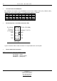
SIXPACK / QUADPACK 7 4 CONNECTOR ASSIGNM ENT • Motor Connectors: • Attention: wrong pinning leads to damage to the pcb • never pull the connectors during operation! PCB edge 1 Analog In (0..5V) Referenz In (22K Pullup, 2 TTL) 3 5V (15mA, 33 OHM) 4 GND 5 PHB2 6 PHB1 7 PHA2 8 PHA1 Phase (coil) A of the motor is wired to connectors PHA1 and PHA2, Phase (coil) B to PHB1 and PHB2. • Electrical Reference Switch The reference switch is connected to the pins „Ref_In“ and „GND“.
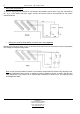
• SIXPACK / QUADPACK Wiring with Stop-Switches To prevent driving beyond the ends of a linear axis stop-switches can be used. They are connected to pin „A_In“ of the motor connector. Again, openers should be used as stop-switches for the reason mentioned above. • Wiring with combined Stop-/Reference Switch when using Openers Mounting the reference switch at one of the ends of the axis it can be concurrently used as stop-switch thus saving the respective stop-switch.
SIXPACK / QUADPACK Power Supply Connector, RS485 RS 232-DSUB-9M and CAN-DSUB-9F 2 1 - 1 CANL 2 - 3 - 4 - 5 5 - 4 2 4 TXD 3 1 3 RXD 2 JP1 GND 3 - 6 GND 7 CANH 8 - 9 - 9 - 8 CTS 7 RTS 6 - 1 2 RS485 / RS232 1 1 2 GND READY OUT (O.C., 100mA, 35V) 2 6 RS485- 1 5 RS485+ 4 GND 3 RS485- 2 RS485+ 1 GND 2 Vcc (+15..40V, 7A) 1 GND RS485-Term.
⇒ SIXPACK / QUADPACK Current Control for QUADpack The maximum coil current for the QUADpack can be set in steps of 0mA (0%), 500mA (33%), 1000mA (66%) and 1500mA (100%). A fine adjustment is done by software.
SIXPACK / QUADPACK 5 SYSTEM 5.1 START 11 UP System Start Up / Notes When the PACK is supplied with power it runs an internal initialization and a self-test of the internal processor-system starts. If executed successfully a “0“ appears in the LED-display after a second. The PACK is operational now and can receive user commands. Defective motor drivers can not be detected by the self test.
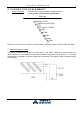
5.7 SIXPACK / QUADPACK Example for a TEST - Setup PC / uC PHA1 PHA2 PHB1 PHB2 M 5V Ref_in A_in RS232 - Cable SIX- / QUADPack Power Supply DC 15 - 40V 5.8 Further Information: For further Information please view our homepage (www.trinamic.com). You will find help under “frequently asked questions”. You also have the possibility to send us an e-mail via a contact sheet located on the same site.
SIXPACK / QUADPACK 13 6 CONTROL 6.1 Control via RS 485 or RS 232-Interface The RS 485 interface is a bi-directional 2-wire interface and can handle up to 255 slave devices in halfduplex mode. The RS 232 interface can be used accordingly, however it is not possible to connect multiple transmitters to the receiver input. The baud-rate is pre-configured to 19200 baud. It can be changed via command.
SIXPACK / QUADPACK simulated by the user. The response address for bytes received via RS 232 and the packet size for transferring received bytes are configured by a separate instruction. To forward bytes received via CAN to RS 232, the CAN-address of the PACK is incremented by 1, i.e. the lower 3 bits are “001“. Every byte which is received with this address will be transferred to the RS 232-interface. 1 to 8 bytes can be transferred at once.
SIXPACK / QUADPACK 15 7 PROGRAMMING 7.1 Hints for Programming ⇒ Strategy for Parameter Setting The Pack can be parameterized for standard applications with a few commands since it is pre-set with default values. However these default values should not substitute a thorough configuration of all parameters in a given application. Normally the following parameters should be configured for your application: ⇒ Setting of Motor Current Configure maximum current (s. CMD $10) and current control (s.
SIXPACK / QUADPACK • The reference switch defines the zero position. The zero position can be moved further into the switch using the nulloffset setting. If testnullbit is set it must be active at the end of T0 and the delay time of the filter. • Activation of the switch is only allowed in the testnullrange to testnull around the zero position. If you reference to the edge of the switch and never exceed the zero position the testnull range can be choosen around 1-2 fullsteps * 16.
SIXPACK / QUADPACK 7.2 17 Examples Attention: All 9 Bytes must be sent to the interface, otherwise the PACK does not recognize the command and waits for the missing bytes. $ indicates that the value is in hexadecimal notation! ⇒ Setting motor parameters CMD $15 contains information about the motor and settings for the reference drive. For more details see Hints for Programming and CMD $15 in the Instruction set! Bit 0 Bit 7 P0 = 0 00000000 MotorNr.1 (0...
SIXPACK / QUADPACK ⇒ Navigating the motor CMD $23 prompts the concerned motor to drive to the position, which stands in P1 ... P4. Pseudocode: sendToPack(address); sendToPack($23); sendToPack(motnr); sendToPack(destinationLSB); sendToPack(destination3rdSB); sendToPack(destination2ndSB); sendToPack(destinationMSB); sendToPack(0); sendToPack(0); // Address of the PACKs // Command for starting a trapezoidal Ramp // Number of the concerned motor (0...
SIXPACK / QUADPACK 19 ⇒ Starting a two axis interpolated movement Linear motions with multiple axes can be driven. For this, the destinations have to be set via CMD $26 and then the trapezoidal Ramp can be started via CMD $50. In the example the axis 1 is navigated to position 10000 and in parallel the axis 2 to position 2000.
SIXPACK / QUADPACK 8 INSTRUCTION SET The instruction code is listed in hexadecimal notation, prefixed with $-sign. “motnr“ substitutes the number of the motor (0=motornr.1 ... 5=motornr.6). Parameters with more than 1 byte are to be transmitted with the least significant byte (bit 0 – 7) first. 8.
SIXPACK / QUADPACK 8.3 21 Setting motor parameters 16 bit or 32 bit parameters, marked with “#”, are transferred with least significant byte (Bit 0 – 7) first. ⇒ Peak current (settings are done for pairs of motors, i.e. each two motors 0 + 1, 2 + 3 respectively 4 + 5 have the same peak current. Only the values set for motor-numbers 0,2 and 4 are valid.) $10 CMD P0 motnr (0...5) P1 value (0..
⇒ SIXPACK / QUADPACK Velocity, Acceleration (amax and vmax are checked permanentely, the Pack promptly reacts to changes) $14 CMD P0 motnr (0...5) P1,2 # amax (1..32767): max. motor acceleration 1/64 amax is accumulated with 500Hz during acceleration to vact: Beginning with vstart the motor is accelerated until vmax has been reached. 0 < amax <= vstart * 64 (default: amax =128) P3,4 # vmax (1..
SIXPACK / QUADPACK ⇒ 23 Motor Parameters Note on the reference search algorithm: Usually the reference switch is logically left, i.e. search orientation is in the direction of descending co-ordinates. However if it is defined as logically right (NullLeft not set) then the driving range is in the area of negative numbers because zero is the largest number on the position scale. Note: To exchange left and right physically, only one phase of the motor has to be polarized reversely.
SIXPACK / QUADPACK ⇒ Reference Search Parameters (change only with motors standing still) Note: Only relevant for fast reference search! $16 CMD P0 motnr (0...5) P1,2 # Vrefmax (1..511): fast reference search velocity: 511 >= vmax >= vrefmax >= vstart P3,4 # mask for reference switch de-bouncing ($0001=0ms,$0003=2ms,...
SIXPACK / QUADPACK 8.4 ⇒ Driving Ramps Query Position and Activity $20 CMD P0 motnr (0...5) P1 response address response CMD P0 P1,2,3,4 # P5 P6 ⇒ $20 motnr (0...5) posact (signed long): current position Current action (0: inactive, 5: ramp, 10: PI-controller, 15: rotation, 20 – 29: reference switch search, 30: mechanical reference) bit 0: stop-status. 1=Stop-condition has occurred. Flag is cleared after read. Query Velocity and Activity $21 CMD P0 motnr (0...
SIXPACK / QUADPACK ⇒ Start trapezoidal Ramp The motor drives from its current position to the target position. The command does not influence the motor, if the motor is still active. To change the target position at any time (on-the-fly) use command $26, and follow it by command $23 with the same target position, to ensure that the motor also starts if it stood still before. The motor will use the optimum way to the target, while considering the motion parameters as well as the current velocity.
SIXPACK / QUADPACK ⇒ 27 Query all Motor Activities, Request delayed Response Each axis can be queried for activity with this command. When delayed response is requested, the PACK will send the response as soon as all concerned motors are inactive. The response contains the actual action of all motors. Attention! In RS 485 mode with multiple slaves this command can lead to bus collisions! To avoid this, the bus should not be used for other transactions while waiting for response.
8.5 ⇒ SIXPACK / QUADPACK Additional Inputs / Outputs Read Motor Input Channels and additional Inputs The analogue channels are prepared for ratiometric measurements of resistive dividers. Channel 6 is the external input, channel 7 measures the voltage supply of the PACK (1V equals value 22). The reference inputs are inverted. $30 CMD P0 channel no (0=channel0 ... 7=channel7). P1 response address Response CMD P0 P1,2 # P3 P4 P5 ⇒ ⇒ $30 channel no (0...7). analogue value (unsigned 0..
SIXPACK / QUADPACK ⇒ 8.6 Function of the ready Output The ready output can be activated (low, open collector), whenever a motor is active (velocity greater than 0) or search of reference. The ready output will be switched within 2 ms after start/end motor movement. The repeatability (jitter) equals approximately the microstep rate during start respectively stop (s. CMD $13).
⇒ SIXPACK / QUADPACK Power-Down modus (Version 1.46 and since Version 1.49) These versions store the actual motor positions as soon as the power supply goes below 13V, if enabled. The motors are stopped, as soon as undervoltage is detected. Thus the devices should not be operated below 15V under normal conditions. The power down state is independent of bit 2 as well observed as set back with bit 3. The power down state which is read also is independent of the stop & save-activation set via bit 2.
SIXPACK / QUADPACK 8.8 31 Service-Functions These functions are not intended for the user and when used improperly the unit can be damaged permanently. ⇒ Enable erasing and writing the Flash-Memory $F2 CMD P0 address for response P1,2,3,4 # magic code Response CMD P0 ⇒ ⇒ Program Flash Memory: This function can only be used after erasing.
⇒ SIXPACK / QUADPACK Read EEPROM $F7 CMD P0 address for response P1,2 Magic Code 2 P3,P4 address P5,P6 value response CMD P0 $F7 1=writing successful Trinamic Motion Control GmbH & Co KG Sternstraße 67 D – 20357 Hamburg, Germany Phone +49-40-51 48 06 - 0 FAX: +49-40-51 48 06 - 60 http://www.trinamic.
SIXPACK / QUADPACK 33 9 Instruction table $10 $11 $12 $13 $14 $15 $16 $17 $18 $19 $20 $21 $22 $23 $24 $25 $26 $27 $28 $29 $2A $30 $31 $32 $33 $40 $41 $42 $43 $44 $45 $CC $50 $F2 $F3 $F4 $F5 $F6 $F7 ⇒ ⇒ ⇒ ⇒ ⇒ ⇒ ⇒ ⇒ ⇒ ⇒ ⇒ ⇒ ⇒ ⇒ ⇒ ⇒ ⇒ ⇒ ⇒ ⇒ ⇒ ⇒ ⇒ ⇒ ⇒ ⇒ ⇒ ⇒ ⇒ ⇒ ⇒ ⇒ ⇒ ⇒ ⇒ ⇒ ⇒ ⇒ ⇒ Peak current Current control Velocity setting Starting velocity Velocity, Acceleration Motor Parameters Reference Search Parameters Write motor characteristics Table Null Point-Offset and -Range PI-Parameter Query Position and Activ