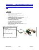
R256 Controller with built-in 256 Microstepping Driver User Manual Version 1.05 RMS Technologies 2533 N. Carson St.
Thank you for purchasing the R256 Controller with Microstepping Driver. This product is warranted to be free of manufacturing defects for one year from the date of purchase. PLEASE READ BEFORE USING Before you begin, ensure there is a suitable DC Power Supply. Do not disconnect the DB-9 cable while power is still being applied to the controller. This will damage the board. Under any circumstances, do not exceed +40 VDC. DISCLAIMER The information provided in this document is believed to be reliable.
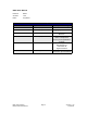
R256 User Manual Product: Version: Date: R256 1.05 4/3/2009 Version History Version Date Description of Changes 1.00 01/11/2006 New User Manual 1.01 08/18/2006 Typographical errors 1.02 01/31/2007 1.03 10/26/2007 1.04 12/14/2007 1.
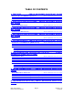
TABLE OF CONTENTS 1. FEATURES...............ERROR: REFERENCE SOURCE NOT FOUND DESIGNER’S KIT WITH RS232 COMMUNICATION.................ERROR: REFERENCE DESIGNER’S KIT WITH USB COMMUNICATION.....................ERROR: REFERENCE DEFAULT SETTINGS...................................................ERROR: REFERENCE SOURCE NOT FOUND SOURCE NOT FOUND SOURCE NOT FOUND 2. ELECTRICAL SPECIFICATIONS....ERROR: REFERENCE SOURCE NOT FOUND DIGITAL I/O SPECIFICATIONS......................................
10. APPENDIX A..........ERROR: REFERENCE SOURCE NOT FOUND PEAK CURRENT VERSUS AMPS/PHASE...............................ERROR: REFERENCE SOURCE NOT FOUND CONNECTING TO THE RS232 CARD (OLD NON-ROHS VERSION).......ERROR: REFERENCE SOURCE NOT FOUND 1. FEATURES • • • • • • • • • • • • • • • Controller with built in Microstepping Driver Operates from +12V to 40V Single 4 wire bus linking up to 16 stepper motors 2.
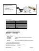
Here is the list of components if you have purchased the optional Designer’s Kit: • USB to RS232 converter card • A switch push button • Opto Sensor • A USB 6 foot long cable RMS part number: USBKIT Default Settings Function (command) Running Current (m) Holding Current (h) Step Resolution (j) Top Velocity (V) Acceleration (L) Position Microstep smoothness (o) Outputs (J) Baud Rate Description 30% of 2.
Storage Temperature Range -20° to 70° C Communication Specifications Interface Type Baud Rate # Bits per character Parity Stop Bit Flow Control RS485 (RS232 or USB with a converter card) 9600, 19200, or 38400 bps 8 Data None 1 None 4. MECHANICAL SPECIFICATIONS Size: 1.932” x 2.192” x 1.228” (49.07 mm x 55.68 mm x 31.19 mm) Weight: 3.6 oz (100 gm) Mounting: Four #6-32 screws, 1.622” x 1.992” (41.20 mm x 50.
Pin # 1 2 3 4 5 6 7 8 9 Color Red Black Brown Black/Whit e Orange Green White Blue Yellow Function +V (Main Power In) I/O RS485B (-) RS485A (+) Input* 1 Switch Closure to GND (IN) GND (-V of main power in) Opto Sensor Phototransistor (IN) I/O Opto Sensor LED (Power Out) 4 3 2 Table 2: Pin Assignments *Inputs are labeled 1, 2, 3 and 4 for programming the ‘Halt’ and ‘Skip’ Commands.
6 Green 3 Brown 2 (GND connect to Power Supply Ground) 3 (RS485B) Table 4 *Where Pin #1 is located here: Figure 4 The USB converter card does not require power (it receives power from the PC). Power is still needed for the R256 controller/driver. RMS Technologies R256 Controller Manual Page 9 Version 1.
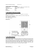
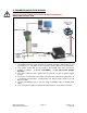
6. CONNECTION SPECIFICATIONS Quick Start DO NOT PLUG IN POWER UNTIL EVERYTHING IS CONNECTED. RS232-485 converter card (Figure 5) 1. The RS232 converter card connects to the R256 using the DB-9 cable that is provided to you. The white 3-Pin connector is placed onto the converter card. 2. Your power supply will be connected to the RS232 card where the green header is located. + is for +12-40VDC, - is for the Power Supply Ground. 3. The 3-pin connector has a green wire for ground.
USB-485 converter card (Figure 6) 1. The USB converter card connects to the R256 using the DB-9 cable that is provided to you. The white 3-Pin connector is placed onto the converter card. 2. Your power supply will be connected to the R256 controller/driver directly. The USB card is powered via the PC. R256’s pin1, Red wire is +1240VDC, pin 6, Green wire is Ground. 3. The motor is connected to the R256 using the other cable that is provided. It is a white 4-pin connector.
Color Functio n (Fig 7) (Figure 8) The table to the right depicts the function Part # 90-018 DB-9 cable with 3-pin header for communication Red A+ Phase Blue APhase Green B+ Phase Black BPhase 7. CONFIGURING AND CONTROLLING THE R256 Table 5 HyperTerminal Setup Please follow these steps in order to properly set up HyperTerminal: 1.
2. Assign a name for your New Connection 3. Determine the correct COM port # by right clicking on “My Computer” and selecting “Properties”. Select the “Hardware Tab” and click on “Device Manager”. Note: if you are using the USB485 converter card, first download driver files (found online: www.rmsmotion.com). You should then see the RMS USB 485 converter card in the “Ports (COM & LPT)” area. If you are connecting via RS232, most likely it is COM1, “Communications Port”. Figure 9 4.
6. Turn on local echo by going to: File Properties Settings tab ASCII Setup: Click on the box for “Echo Typed Characters Locally” and click on the box for “Send Line ends with line feeds”. Click “OK”. 7. Now you can type your commands Figure 11 Example command: /1A10000R • This will run unit #1 to the Absolute position 10000 • You can check the address of your driver by checking the dial at the top of the driver.
Setting the Current CAUTION! DO NOT SET THE CURRENT 1.4 TIMES ABOVE THE MOTOR’S RATED CURRENT. In order to set the correct current for your motor, you must program the specified amount in HyperTerminal Current is set based on the Maximum amount of current the controller board can output, which is 2.0 Amps Peak. Since all drivers only speak in terms of Amps Peak current, we must translate from the motor’s rated current (Amps/Phase or Amps RMS) to peak current.
WARNING!: Setting the Current to a value greater than 1.4 times the Motor’s rated current will damage your motor, and may overheat the controller. Connecting Multiple R256 Controllers If using the RS232-to-RS485 converter card, daisy chain all four wires: power, ground, RS485+ and RS485- prior to plugging into the converter card. Figure 12: Connection using RS232 Converter Card If using the USB485 converter card, connect all the power and ground lines on the units to the main power supply.
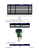
Changing the Address of the Controller Use a screwdriver to turn the dial so the arrow points to the desired Address. Use this number when programming commands. For example, /1P1000R Figure 14: Address Dial Note: New RoHS compliant boards have a Black dial instead of a Red one. Connecting the Accessory Pieces If you have purchased the Designer’s Kit, there is a Red Push Button and an Optical Sensor included. Follow the schematics below in order to properly assemble accessory pieces.
Input 3 Pin 7 Input 4 Pin 5 Table 7 Any of the four inputs can be connected to a push button.
Optical Sensor Figure 16: Opto Sensor Connection Schematic The Opto Sensor uses Pins 6, 7, and 9. Use the following table to solder the corresponding wires. Optical Sensor DB9 Cable Green Green Black Green Red Yellow White White Table 8 In order to program the motor to home towards your optical sensor, simply use the Z command and state the max number of steps you want it to search for home. The unit will either stop at the opto sensor or when it finishes moving your designated number of steps.
Encoder Usage The R256 can also be used as reference to home by connecting to an US Digital E2 Encoder. The pinouts are as follows: Pin Number Function 1 Ground 2 Index 3 Channel A 4 + 5 VDC 5 Channel B Table 9 The E2 encoder requires a separate +5 Volt power supply, as the R256 controller cannot provide a strong enough source of power. In order to use the Indexer as a reference to home, connect Pin 2 from the encoder to one of the inputs on the controller.
8. MOTOR CONNECTIONS Step Motors have 4, 6, or 8 wires. To better understand how to connect your step motor with your R256 Controller, follow the Figures below for the corresponding motor. NOTE: The dots indicate the starting position of the wires when wound. 4 Lead Wire Motor Connection Connect one set of windings to the A terminals. Connect the other set of windings to the B terminals. If the set of windings is unclear, take a pair of wires; use an ohmmeter to check for continuity.
6 Lead Wire Motor Connection (Full-Winding) For a full winding connection, use both end wires, the center tap is ignored. (NC: No Connection). Figure 20: 6 Lead Wire Full Winding Connection 8 Lead Wire Motor Connection (Parallel Connection) Eight wire motors can be connected in two ways: Parallel and Series. When in parallel, the wires are simply connected such that the beginning of each winding are connected together.
9. Troubleshooting & FAQ Cannot Type anything in HyperTerminal: Is the correct COM Port selected? Are you using Windows 95? Windows 95 has had problems with its HyperTerminal. Use an operating system of Windows 98 or higher. Are you working on a Laptop? Sometimes there is a shift in Ground on Laptop Serial Ports. Pin 5 on the Serial Port is Ground. Make sure that this is connected to a true ground.
Halt Command (H01) Issues There are known issues involving the Halt command (i.e., H01) when stored in memory location zero. Upon power up, the remaining command string after the Halt command might be executed if the user types in a new command. If memory location zero is not being used, the user is advised to always clear everything in memory by typing /1?9. Otherwise, the user may terminate the remaining command string in the buffer by issuing a /1T.
Peak current versus Amps/Phase Where does the 1.4 times come from? Current is continuously changing when a motor steps. If the motor is rated for 1.0 A/Ph, it may receive 0 Amps, 1 Amp, 1.4 Amps, or anything in between if you are microstepping. For ease of explanation, we will look at the current waveform when we half step, or set the driver/controller to 2x microstepping.
1.41 AMP (√2) 1 AMP 1 AMP Take a look at position #7. If we were to draw the arrow at position 7 as the hypotenuse of a triangle, it would look like the triangle to our left. Recall from geometry a 90°-45°-45° triangle is a 1-1-√2 combination. The √2, or 1.4 value is also the radius of the dotted circle shown above. Therefore, during certain steps, Phases A or B will receive 1.4 Amps of current. But the average, or RMS current throughout these 8 steps is only 1.0 Amps.
7. The RS232 converter card connects to the R256 using the DB-9 cable that is provided to you. The red 4-Pin connector is placed onto the converter card. 8. Your power supply will be connected to the RS232 card where the green header is located. + is for +12-40VDC, - is for the Power Supply Ground. 9. The motor is connected to the R256 using the other cable that is provided. It is a white 4-pin connector. The Red wire is A, Blue is A Bar, Green is B, and Black is B Bar. 10.