RMT Ltd RMT Ltd Joint Stock Company Optical Unit DX6106 Series User Guide 2002 Rev. 1.
DX6106 RMT Ltd Edition April 2002 Copyright All right reserved. Reproduction in any manner, in whole or in part is straightly prohibited without written permission of RMT Ltd The information contained in this document is subject to change without notice.
RMT Ltd DX6106 Contents 1. Introduction 2. Theory of Operation Principles of Operation Design Features Operation Overview 3. Construction of Optical Unit Gas Sampling Cell Optocomponent 6102 Optocomponent Mating Module Preamplifier Thermoelectric Cooler Thermistor Light Emitters EEPROM EEPROM Data Format 4. Installation Tips 5. Calibration Preparation Zero Adjustments Re-Calibration 6. Maintenance Optics Cleaning 7. Standard Kit 8. Specifications 9.
DX6106 C-2 RMT Ltd REV. 1.
RMT Ltd DX6106 1. Introduction The company RMT Ltd introduces new DX6106 series of Optical Units for gas measurement systems. The principle of operation is based on selective absorption of IR radiation by gas molecules. The differential double frequency optical scheme provides high accuracy in wide ranges of humidity and temperature due to the internal thermostabilization. New type of middle infrared combined optocomponent with built-in thermoelectric cooling is used.
DX6106 1-2 RMT Ltd REV. 1.
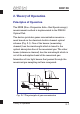
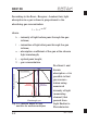
RMT Ltd DX6106 2. Theory of Operation Principles of Operation The NDIR (Non-Dispersive Infra-Red Spectroscopy) measurement method is implemented in the DX6106 Optical Unit. The device provides gases concentration measurement based on the classical double channel optical scheme (Fig. 2.1). One of the beams (measuring channel) has the wavelength which is tuned to the optical absorption line of the measured gas.
RMT Ltd DX6106 According to the Beer-Bouguer-Lambert law, light absorption in a gas volume is proportional to the absorbing gas concentration: where I = I0 × e -a L X I0 – intensity of light before pass through the gas I volume; – intensities of light after pass through the gas volume; Relative response a – absorption coefficient of the gas at the chosen light wavelength; L – optical pass length; X – gas concentration. At a fixed L and 1.
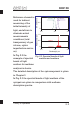
RMT Ltd Emission band 1.0 Reference channel Measuring channel 0.5 0 2.0 Relative absorption Reference channel is used for indirect measuring of the initial intensity of light, and allows to eliminate actual measurements conditions (total transparency of gas volume, optics imperfection and so on). DX6106 3.0 4.0 3.0 4.0 1.0 Methane 0.5 0 2.0 Wavelength, µm In Fig. 2.2 the Fig. 2.3.
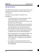
DX6106 RMT Ltd Design Features The DX6106 Optical Unit is specially designed for a fast response, high sensitivity, low noise and low power consumption. A number of design features contribute to the performance : The infrared sources are special narrow-band pulsed Light Emitters which operate in microsecond range. The light sources have long life (more then 10,000 hours).
RMT Ltd DX6106 Operation Overview The subsequent description assumes User has already developed, manufactured and connected to the Optical Unit some electronic device for Optical Unit management. (See recommendations in Chapter 3). The order of measurements with DX6106 device is as follows: 1. Firstly, individual calibration of device is required with using of standard gas mixtures. The Detector output signal is non-linear with respect to measuring gas concentration.
RMT Ltd DX6106 Y= D0 D X = A0 + A1 × Y + A2 × Y 2 + A3 × Y 3 + A4 × Y 4 Calculated coefficients A0 … A4 of polynomial expression and zero ratio D0 may be stored into device internal on-board EEPROM memory. The first calibration is made by Manufacturer. The factory standard calibration uses not less than 5 standard gas mixtures.
RMT Ltd DX6106 3. To preserve high accuracy of the device it is necessary to do “zero” adjustments periodically as recommended in Chapter 5. 4. Periodicity of device recalibration is 1 year. It could be done at the factory of Manufacturer, or by a User.
DX6106 2-8 RMT Ltd REV. 1.
RMT Ltd DX6106 3. Construction of Optical Unit The DX6106 Optical Unit (Fig. 3.1 and 3.2) consists of an isolated gas sampling cell (the spherical mirror and the flat mirror with a hole are placed at the end sides) and a new generation integrated optopair with 6102 electronic module. The 6102 Optocomponent Mating Module is connected to optopair’s leads and is fixed with two screws on a bottom cover of the gas sampling cell. Fig. 3.2.
RMT Ltd DX6106 Gas Sampling Cell The body of gas sampling cell is made of anodized aluminum alloy (Fig. 3.3). It has two gas inlets with 5.0 mm internal diameter. The gas sampling cell can be easily Fig. 3.3. DX6106.C40 gas sampling cell disassembled for service of internal optics (mirrors and optopair). For this purpose both the top and bottom covers can be removed and the optical components extracted out. The gas sampling cell design is shown in Fig. 3.4.
RMT Ltd DX6106 The optical scheme of gas cell is represented in Fig. 3.5. Flat Mirror with a hole Gas Integrated optopair Outlet brunch pipe Spherical Mirror Inlet brunch pipe The main parameters of gas sampling cell are in Table 3.1 Table 3.1. Main parameters of gas Parameter Value No. of passes 4 Total path length, mm 80 Internal volume, ml Construction of Optical Unit 10.
RMT Ltd DX6106 The outline dimensions of DX6106.C40 gas sampling cell are shown in Fig. 3.6. 42 27 27 36.5 40 Fig. 3.6 DX6106.C40 gas sampling cell outline dimensions (in millimeters) 3-4 REV. 1.
RMT Ltd DX6106 Optocomponent The new generation OPRI optopair consists of three optoelements integrated into one case : two narrow-band light emitters (of about 0.1 µm emission band) and one wide-band photodetector. The optopair consists of two special solid state light emitters (light sources) and one sensitive element (photodetector). The peak emission wavelength of one light emitter is near the absorption band of measured gas (measuring channel).
RMT Ltd DX6106 As an example, the parameters of optoelements for methane (CH4) measurements are 12 11 10 t° 1 R 2 introduced in the table bellow: M 4 8 7 + 3 9 5 6 Fig. 3.8. OPxxx optopair pins layout (top view) Element Peak wavelength [ µm ] Bandwidth [ µm ] Measuring channel emitter Reference channel emitter Photodetector 3.23 2.98 3.3 0.1 0.1 2.5 The above table is illustrated with Fig. 3.9. 1.0 Relative response Photodetector 0.5 Reference channel Measuring channel 0 2.0 3.
RMT Ltd DX6106 6102 Optocomponent Mating Module The 6102 Optocomponent Mating Module (Fig. 3.10) provides: preamplification of photodetector’s signals, light emitters driving, Fig. 3.10. 6102 Optocomponent Mating Module power supply of photodetector and thermistors with precise voltage. The connectors and optopair location at the 6102 Module’s board is shown in Fig. 3.11. The outline dimensions of 6101 Module are given in Fig. 3.12.
RMT Ltd DX6106 X2 8 SCL SDA X2 2 TEC X2 6 +ELED X1 5 OUTS X1 7 OUTT 3 4 6 8 GNDA GNDA GNDA GNDA Filter X1 2 +5VIN Filter X1 1 –5VIN X2 4 GATEM X2 5 GATER X2 3 SOURCE X2 1 GND X2 7 t° + EEPROM X1 X1 X1 X1 Legend t° – TE cooler – Light Emitter – MOSFET switch – thermistor – Photodetector – amplifier Fig. 3.13. Functional Diagram of 6102 Optocomponent 3-8 REV. 1.
RMT Ltd DX6106 The functional diagram of the 6102 module is drawn in Fig. 3.13. System interface connectors’ pins assignment is given in Tables 3.2 and 3.3. Table 3.2.
RMT Ltd DX6106 Preamplifier The preamplifier’s circuit diagram is presented in Fig. 3.14. +5V X1 1 +5VIN –5VIN X1 5 OUTS 3 4 6 8 GNDA GNDA GNDA GNDA X1 2 X1 X1 X1 X1 Fig. 3.14. Simplified diagram of preamplifier of the 6102 module The preamplifier alternatively processes the signals of measuring and reference channels. The preamplifier output signal should be conditioned and then digitized by A/D converter (ADC) with not worse than 12 bit resolution.
RMT Ltd DX6106 +5V X1 1 +5V –5V X1 5 Attenuator X1 2 X1 X1 X1 X1 ADC Microcontroller DX6106 Optical Unit 3 4 6 8 Fig. 3.15. Output signal processing Within the gas concentration varying scale, the output signal of measuring channel changes by order of value. To preserve accuracy at large measuring gas concentrations it is necessary to use an external amplifier with a variable gain. It is to coordinate the amplified signal with an ADC range. Alternatively, an attenuator may be used.
RMT Ltd DX6106 The preamplifier typical output signal waveform is showm in Fig. 3.16. MTB = 20 HS CH1 = .5V Fig. 3.16. Typical output signal waveform 3-12 REV. 1.
RMT Ltd DX6106 Thermoelectric Cooler The TEC circuit diagram is presented in Fig. 3.17. X2 2 TEC X2 1 GND Driving by TE cooler requires particular attention. First of all, the operation of TE cooler directly affects performance parameters of Optical Unit and gas sensor based on it. Fig. 3.17. Schematics of TE cooler in Second, the TE cooler is the component which consume the largest part of power (Fig. 3.18). The output signal of Photodetector depends very much on its temperature (Fig. 3.19).
RMT Ltd DX6106 Power, W 2.0 1.5 1.0 0.5 0 –20 –15 –10 –5 0 5 10 Temperature, °C Fig. 3.18. TEC power consumption vs operating temperature Output, V 1.4 1.2 0.8 Um 0.6 1.0 0.8 0.6 0.4 0.4 Ur Um/Ur Um/Ur Ratio 1.6 0.2 0.2 0 –15 –10 –5 0 5 0 10 Temperature, °C Fig. 3.19. Typical preamplifier output vs operating temperature 3-14 REV. 1.
RMT Ltd DX6106 consumption; at higher temperature the output signals (and signal/noise ratio) are lower. The Optical Unit housing has been designed for additional heat dissipation from warm side of working TE coolers. The maximal heat dissipation is 2 W. At Ta-Top > 40 °C it is necessary to use additional heat dissipation - a bigger heat sink (optional available) or a fan. A developer of thermo-stabilization algorithm has to take into account that time constant of TE cooler is approximately 2 s.
DX6106 RMT Ltd If step-down DC/DC converter is used, the VCC voltage should be not less than 7V to provide the appropriate range of TEC control voltage. The maximum converter’s output current is determined by TECs characteristics behavior. (See Fig. 3.21). Fig. 3.21. Maximal temperature difference vs operating current for 1MT04-059-16. (At zero heat load) As one can see in this diagram, there is some peak current value, the efficiency of TE cooler falls down after that.
RMT Ltd DX6106 TE Cooler Specifications TAMB = +20°C Parameter Units Min Typ Max Comments Electrical Parameters Operating T °C Operating Voltage V Operating Current A Resistance Ohm –40 6.8 0.5 11.1 11.7 12.
DX6106 3-18 RMT Ltd REV. 1.
RMT Ltd DX6106 Thermistor UREF RT Filter X1 2 +5VIN X1 7 OUTT 3 4 6 8 GNDA GNDA GNDA GNDA t° For a TE cooler temperature controlling NTC thermistor is mounted onto the cold side of a TE cooler. This thermistor is applied in a scheme with serial loading resistor RL and a reference UREF (Fig. 3.22). RL C X1 X1 X1 X1 Fig. 3.22. Thermistor connection in the 6102 Component list Designation Value RT 2.2 kW ±5% RL 3.83 kW ±0.1% C 0.
RMT Ltd DX6106 30 Resistance, kOhm 25 20 15 10 5 0 –40 –20 0 20 Temperature, °C 40 60 80 Fig. 3.23. Calibration of thermistor vs measured temperature The curve in Fig 3.23 is plotted on the basis of the fundamental equation R = R0 e ( 1 1 b T -T 0 ) (3.1) where b R0 3-20 - Beta Constant, - resistance at standard temperature T0. REV. 1.
RMT Ltd DX6106 The output signal from thermistor scheme depends on its resistance as : æ ö U TR = U REF çç R L ÷÷ è R L + RT ø (3.2) One can see that the temperature measurement accuracy depends directly on UREF. So the voltage +5VIN on the pin X1/2 must be stable. With the help of equations (3.1) and (3.2) we obtain the plot in Fig. 3.24. 5 Output, V 4 3 2 1 0 –40 –20 0 20 40 60 80 Temperature, °C Fig. 3.24.
DX6106 RMT Ltd It is obvious that the scheme responds to temperature in a nonlinear manner. At the same time over a limited temperature range it is possible to consider the scheme response as linear. It is also obvious that the solution of this problem should be based on the usage of a microcontroller. A look-up table for temperature measurements linearization must be formed in the external memory. The table may be located in the Optical Unit’s EEPROM or in another memory chip.
RMT Ltd DX6106 DX6106 Optical Unit RT +5V X1 2 t° Filter ADC X1 7 RL C X1 X1 X1 X1 3 4 6 8 Fig. 3.25. Typical thermistor usage Thermistors Specifications TAMB = +20°C; VCC = 5±5% V Parameter Units Resistivity Beta-Constant kOhm K·10-3 Construction of Optical Unit Min Typ Max 2.09 2.2 2.31 2.9 3.1 3.
RMT Ltd DX6106 Light Emitters + RE C RS RG RG X2 6 +ELED X2 4 GATEM X2 5 GATER X2 3 SOURCE X2 1 GND Fig 3.26. LED drive switches Electronic scheme for Light Emitters driving is shown in Fig. 3.26. The MOSFET transistors are used as a switch keys which are driven by TTL logic levels. The resistors RG in a gate circuits fix closed state of transistors at the absence of activity from external electronic scheme. The sense resistor RS (0.
RMT Ltd DX6106 T = +25°C 5 4 ILED, A Power Supply 5 V (+4…+6 V are available) through resistor R charges the capacitor C in time duration between pulses. Total capacity (the capacitor C and available external ones) must be enough for pulse current stability. 3 Safe Area 2 1 0 2 4 6 ULED, V Fig. 3.27. Typical volt-ampere Component list Designation Value RE 4.7 W ±5% RS 0.22 W ±5% C 2 ´ 220 mF 6.
RMT Ltd DX6106 DX6106 Optical Unit X2 6 DAC X2 4 DAC X2 5 RS RG RG Microcontroller + RE C X2 3 X2 1 Fig. 3.28. Typical LED control circuit It is advisable in the real design to use some number of analog multiplexors to distribute, for example, the signal of singe DAC into two OPs or output signal of one OP into two MOSFET gates. It will enable to spare some equipment. The current limiting and stabilizing circuit must be implemented essentially into LED driving circuit.
RMT Ltd DX6106 is easy to plot the load line (the curve in Fig.3.X) and to see that the forward current through the LED can run up to 5 amperes if +ELED voltage is chosen as 6V. There is some difference of a photodetector’s response to measuring and reference channel LEDs emittance. To decrease the dynamic range losses, the emitting powers of both LEDs should be balanced.
RMT Ltd DX6106 EEPROM EEPROM SCL X2 8 SDA X2 7 The standard Electrically Erasable PROM (EEPROM) 24LC64 chip with two wire serial Fig. 3.21. I 2C interface connection I2C interface is placed on Optical Unit's PCB. It is used for storage of the Optical Unit identification code, calibration data and some additional data for operation of the unit. Additional data are used for operation of the Optical Units with manufacturer's controller DX6101.
RMT Ltd DX6106 The detailed description of 24LC64 transfer protocol is possible to obtain, for example, from Data sheet retrieved from Microchip Corporation Web site (http://www.microchip.com). Besides the similar memory devices, are manufactured by other corporations. For example Atmel, Fairchild, ST Microelectronics, etc.
DX6106 RMT Ltd EEPROM Data Format Various operating parameters can be stored in onboard EEPROM circuit: calibration data, synchronization parameters, measuring mode presets, TE cooling algorithm presets, Optical Unit identification. See recommended EEPROM data structure in Table 3.4. The formats of the First Calibration Data Block is given in Table 3.5. Formats of other reserved (if applied) Calibration Data Blocks are the same as the first one. 3-30 REV. 1.
RMT Ltd DX6106 *) Item Table 3.4.
DX6106 3-32 RMT Ltd REV. 1.
RMT Ltd DX6106 4. Installation Tips There are two external power sources required for Optical Unit supply. An external +5V and -5V DC power sources with ±2.5% output tolerance are required for Optical Unit supply. The operating current must be not less than 7.5 mA. The power supplies are to be connected to pins X1/1 and X1/2. They are necessary for supply of: preamplifier of Photodetector, thermistors and sensitive elements of Photodetector, EEPROM.
RMT Ltd DX6106 DX6106 Optical Unit +5V / –5V Converter X1 1 +5V +6¼9.5 V Linear Regulator X1 2 X1 5 X1 7 Control & Measuring Circuits Power supply 0 X2 2 X2 6 X2 4 X2 5 X2 3 X1 X1 X1 X1 3 4 6 8 X2 1 LED & TE Coolers Drivers Signal Ground Power Ground Shielding Ground Fig. 4.1. DX6106 power supplies connection 4-2 REV. 1.
RMT Ltd DX6106 5. Calibration Preparation First of all User should prepare the set of calibration gases. The number of calibration gases should be at least two more than the desirable polynomial order (See Chapter 2). In turn the order of a polynomial determines accuracy of approximation, and hence the measurement accuracy.
DX6106 RMT Ltd Any other sets of standard samples User can apply according to own reasons. But be sure that the samples are within specified measurement range and the customer standard gases provide accurate calibration. As a “zero” gas one can use any standard pure gas. Argon (Ar) or Nitrogen (N2) are quite suitable. As other concentrations, the mixture of measured gas with the “zero” gas is usually used. Prepare some portions of plastic tubes for gas bottles connection with Optical Unit’s gas inlets.
RMT Ltd DX6106 Zero Adjustments To ensure the high accuracy, simple adjustment can be made during operation to adjust “zero” ratio D0. The procedure requires to flow up any "zero" gas through the gas sampling cell. The new D0 coefficient should be stored into EEPROM in place of old value after the completing adjustment procedure (See Chapter 2).
DX6106 RMT Ltd Re-Calibration In standard option, the DX6106 Optical Unit is delivered with one calibration data. The calibration is made at optimal operating temperature. User can make re-calibration at any time. It is possible to do this at other operating temperatures, with larger set of reference gases (larger order polynomial) and to replace stored data by the new one. According to customer demands the re-calibration could be done by Manufacturer on request.
RMT Ltd DX6106 6. Maintenance Optics Cleaning If the output signal of either channels (or both) became appreciably less than usually, the Optical Unit’s optics is most likely to require cleaning. Cleaning of optics is executed with the help of suede and the special optic cleaning fluid. For optics cleaning the DX6106 Optical Unit must be disassembled. Remove screws from each end face of the Optical Unit. Remove the covers (Fig. 6.1).
RMT Ltd DX6106 The Optical Unit after disassembling is shown in Fig. 6.2. Fig. 6.2. DX6106 Optical Unit with the The spherical mirror is glued to the top cover. Do not try to rip it off. Clean now the window of the optopair, spherical mirror, internal mirror (with a hole) from both sides. Wait some minutes and assemble the Optical Unit in the reverse order. 6-2 REV. 1.
RMT Ltd DX6106 7. Standard Kit Item # Code Quan.
DX6106 7-2 RMT Ltd REV. 1.
RMT Ltd DX6106 8.
RMT Ltd DX6106 Carbon Dioxide (CO2) Sensor*) Concentration range 1) 0...1000 ppm 0...5 % vol 0...20 % vol Noise level 2, 3) < 3 ppm < 0.15 % < 0.15 % Accuracy 3) 10 ppm 0,5 % 0,5 % Zero drift 3) 0.02 % Hydrocarbons (CmHn) Sensor*) Concentration range 1) 0...1000 ppm Noise level 2, 3) < 2 ppm < 0.1 % Accuracy 3) 10 ppm 0,5 % Zero drift 3) *) If to use with DX6101 controller. 1) Optional ranges up to 100% vol. are available. 2) At Averaging Time Constant =0.2 s.
RMT Ltd DX6106 9. Ordering Guide XXXXXX . XX . XXX . X Gas Sampling Option A - Aspiration D - Diffusion Concentration Range The largest concentration value, in ppm, includes 2 significant digits followed by the number of zeros to follow Gas Code Code Gas 01 CO2 02 CnHm 03 CH4 04 CO 05 H2O Part Number Example: DX6106.01.504.A [DX6106] DX6106 Series, [01] CO2 Gas Option, [504] [A] Ordering Guide 0...5.0×104 ppm (0...
DX6106 9-2 RMT Ltd REV. 1.
RMT Ltd DX6106 RMT Ltd. Leninskij prosp. 53, Moscow 119991 Russia phone: 095-132-6817 fax: 095-135-0565 e-mail: rmtcom@dol.ru http://www.rmtltd.