
Datasheet


Absolute Maximum Ratings at Ta=25℃
Notes:
a. Luminous intensity is measured with a light sensor and filter combination that approximates the CIE eye-response curve.
b. 2θ
1/2
is the o-axis angle where the luminous intensity is 1⁄2 the peak intensity.
c. The dominant wavelength (λd) is derived from the CIE chromaticity diagram and represents the single wavelength which
defines the color of the device.
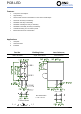
PCB LED
Notes:
a. Derate linearly as shown in derating curve.
b. Duty Factor = 10%, Frequency = 1 kHz.
Electrical Optical Characteristics at Ta=25
℃
Parameters Symbol Max. Unit
Power Dissipation
P
d
60 mW
Peak Forward Current
(a)
I
FP
100 mA
DC Forward Current
(b)
I
F
25 mA
Reverse Voltage V
R
5 V
Operating Temperature Range T
opr
-40
℃
to +80
℃
Storage Temperature Range T
stg
-40℃ to +85℃
Soldering Temperature T
sld
260℃ for 5 Seconds
Parameters Symbol Min. Typ. Max. Unit Test Condition
Luminous Intensity
(a)
Iv 90 160 --- mcd IF=20mA
Viewing Angle
(b)
2θ
1/2
--- 80 --- deg. IF=20mA
Peak Emission Wavelength λp --- 573 --- nm IF=20mA
Dominant Wavelength
(c)
λd --- 571 --- nm IF=20mA
Spectral Line Half-Width △λ --- 20 --- nm IF=20mA
Forward Voltage VF 1.6 2.0 2.4 V IF=20mA
Reverse Current IR --- --- 10 µA VR=5V
Distrelec Schweiz AG, Grabenstrasse 6, 8606 Nänikon, Switzerland, T +41 44 944 99 11, info@distrelec.com, distrelec.com