
Datasheet


SMD LED
Because different board designs use different number and types of devices, solder pastes, reflow ovens, and
circuit boards, no single temperature profile works for all possible combinations.
However, you can successfully mount your packages to the PCB by following the proper guidelines and PCB-
specific characterization.
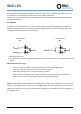
Drive Method
An LED is a current-operated device. In order to ensure intensity uniformity on multiple LEDs connected in
parallel in an application, it is recommended that a current limiting resistor be incorporated in the drive circuit,
in series with each LED as shown in Circuit A below.
Circuit model A Circuit model B
LED LED
a. Recommended circuit.
b. The brightness of each LED might appear different due to the differences in the I-V characteristics of those
LEDs.
ESD-damaged LEDs will exhibit abnormal characteristics such as high reverse leakage current, low forward
voltage, or “no lightup” at low currents. To verify for ESD damage, check for “lightup” and Vf of the suspect
LEDs at low currents. The Vf of “good” LEDs should be >2.0V@0.1mA for InGaN product and >1.4V@0.1mA
for AlInGaP product.
• Use of a conductive wrist band or anti-electrostatic glove when handling these LEDs.
• All devices, equipment, and machinery must be properly grounded.
• Work tables, storage racks, etc. should be properly grounded.
• Use ion blower to neutralize the static charge which might have built up on surface of the LED’s
plastic lens as a result of friction between LEDs during storage and handling.
ESD (Electrostatic Discharge):
Distrelec Schweiz AG, Grabenstrasse 6, 8606 Nänikon, Switzerland, T +41 44 944 99 11, info@distrelec.com, distrelec.com