
Datasheet

Ceramic Disk Capacitors
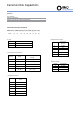
Description
Symbol
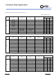
(mm)
REMARK
Carrier Tape Width W
18±0.5
Position of Sprocket Hole W1
9±0.5
Pitch of Component P 12.7 Ref.
Pitch of Sprocket hole Po
12.7±0.3
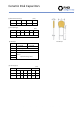
Length from Hole Center to Lead P1
5.1±0.7
P1=3.18± 0.7 refer to F=6.35±0.8
3.85±0.7
3.18±0.7
Length from Hole Center to Component Center P2
6.35 Ref.
Diameter of Sprocket Hole Do
4±0.3
Diameter of Body D Refer Capacitance Range Chart
Diameter of Lead Wire D
0.55±0.05
Lead Spacing F
2.5±0.8
5±0.8
6.35±0.8
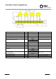
Lead Crimped Height H
16
Tolerance
1.5
1
20
Top of Component Height H1
32.25max.
Coating extension on Lead G
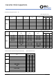
Refer Capacitance Range Chart
Thickness of Body T
Refer Capacitance Range Chart
Distrelec Schweiz AG, Grabenstrasse 6, 8606 Nänikon, Switzerland, T +41 44 944 99 11, info@distrelec.com, distrelec.com