
Datasheet

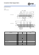


Ceramic Disk Capacitors
Item
Temperature Compensating
Measuring Condition
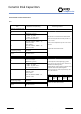
Resistance to Soldering heat
C
2.5
﹪
or 0.25pF
Whichever is greater
The lead wire is immersed in the melted solder
1.5mm to 2mm from the main body at 260 5
℃
for 10 0.5sec.
Let sit at room temperature for 24 2 hrs. then
measure.
Perform the initial measurement.
C≧30pF:Q≧1000
C<30pF:Q≧400 + 20 × C
(C is nominal capacitance)
More than 10GΩ or 500MΩ ‧μ F ,
whichever is less.
16Vdc product:
More than 10GΩ or 100MΩ ‧μ F ,
whichever is less.
Thermal shock
C
2.5
﹪
or 0.25pF
Whichever is greater
Fix the capacitor to the supporting jig in the
same manner and under the same conditions as
(Resistance to Soldering heat ).
Perform the five cycles according to the four heat
treatments listed in the following table.
Remove and let sit at room temperature for 24
2 hrs., then measure.
Step 1 2 3 4
Temp.
(℃)
Min.
Operating
Temp.
Room
Temp.
Max.
Operating
Temp.
Room
Temp.
Time
330
15
330
15
Perform the initial measurement.
Q
I.R.
C≧30pF:Q≧1000
C<30pF:Q≧400 + 20 × C
(C is nominal capacitance)
More than 10GΩ or 500MΩ ‧μ F ,
whichever is less.
16Vdc product:
More than 10GΩ or 100MΩ ‧μ F ,
whichever is less.
Environmental and Test Characteristics
NPO
Q
I.R.
Withstanding voltage
No abnormalities
No defects
Exterior
Exterior
Withstanding voltage
No abnormalities
No defects
Distrelec Schweiz AG, Grabenstrasse 6, 8606 Nänikon, Switzerland, T +41 44 944 99 11, info@distrelec.com, distrelec.com