, OWNER S MANUAL CHECK Table of Contents 1. Safety Precautions and Warnings --------------------------------------------------------3 2. Product Information ----------------------------------------------------------------------------3 2.1 About the Code Reader -------------------------------------------------------------------3 2.2 Product Features -----------------------------------------------------------------------------4 2.
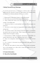
CHECK , OWNER S MANUAL 1.Safety Precautions and Warnings To prevent personal injury or damage to vehicles and/or the code reader, read this instruction manual first and observe the following safety precautions at a minimum whenever working on a vehicle: 1. Always perform automotive testing in a safe environment. 2. Wear safety eye protection that meets ANSI standards. 3. Keep clothing, hair, hands, tools, test equi pment, etc, away from all moving or hot engine parts. 4.
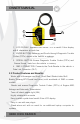
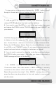
, OWNER S MANUAL CHECK 1 4 2 3 1. LCD DISPLAY- Indicates test results. It is a backlit 2-line display with 8 characters on each line. 2. ENTER BUTTON- Retrieves and Scrolls throug h Diagnostic Trouble Codes (DTCs) stored in the Vehicle’s systems. 3. SCROLL BUTTON- Erases Diagnostic Trouble Codes (DTCs) and “Freeze Frame” data from the vehicle’s memory. 4. OBD II CONNECTOR- Connects the Code Reader to the vehicle’s Data Link Connector (DLC). 2.
, OWNER S MANUAL CHECK • Small in size and conveniently fits in your palm • Specially designed for DIYers and car-owners • Safely communicates with the on-board computers • No batteries needed-powered via OBD II cable • One-year warranty 2.3 Vehicle Coverage The T45 VW/AUDI Code Reader is specially designed to work with most Volkswagen and Audis sold Worldwide of 1990 or newer models. If a VW/AUDI has a 16-pin "OBD-II style" Data Link Connector(DTC), the code reader will certainly work.
, OWNER S MANUAL CHECK observed on the display. If you press "SCROLL" button, the "1. ENGINE" message is observed again on the display. MENU: ----> 1. ENGINE READY ? YES NO… If an ERROR! message shows up, turn the ignition off for about 10 seconds, check if the code reader’s OBDII connector is securely connected to the vehicle’s DLC, and then turn the ignition back to on. Repeat the procedure from step 5.
, OWNER S MANUAL CHECK To view previous codes,press and release the “ENTER” button to scroll throug h to the end,and then scroll starting from the first of the list. 00260 01/08 7. Look up part 4 for Diagnostic Trouble Code Definitions. Match the retrieved DTC(S) with those listed and read the definitions. 8. If you wish to erase the DTC(s) or exit to the next system, then press and release the SCROLL button. The LCD display will read “ERASE? for your selection.
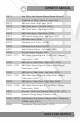
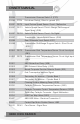
, OWNER S MANUAL CHECK 4. Diagnostic Trouble Code (DTC) Definitions The following Diagnostic Trouble Code (DTC) definitions lists provide both VAG and SAE (OBD-II) trouble codes. For codes not listed in this table, consult the vehicle's service Manual.
CHECK , OWNER S MANUAL 00271 See VW or Audi Service Manual,Repair Group 01 (Depends on Which Vehicle Is under Test) 00273 ABS Inlet Valve - Rig ht Rear (N133 00274 ABS Outlet Valve - Left Rear (N134) 00275 ABS Outlet Valve - Rig ht Rear (N135) 00276 ABS Outlet Valve - Rig ht Rear (N136) 00277 ABS Inlet or Outlet Valve - Left Front (N137) 00278 ABS Main Valve (N105) 00279 Differential Lock Valve 1 (N125) 00280 Differential Lock Valve 2 (N126) 00281 Vehicle Speed Sensor - No Signal (G6
, OWNER S MANUAL 00295 00296 P1704 00297 P0715 00297 P0721 CHECK Transmission Pressure Switch 2 (F175) Kick-down Switch - Short to ground (F8) Input/Turbine Speed Sensor Circuit - Malfunction Vehicle Speed Sensor Circuit - Range/Performance Signal Noisy (G38) 00297 P0722 Vehicle Speed Sensor Circuit - No Signal 00297 Transmission Vehicle Speed Sensor (G38) 00298 Rear Differential Lock Switch -E121 00299 Transmission Shift-Range Program Switch - Short Circuit -E122 00300 P0712 Transmission Fluid T
CHECK , OWNER S MANUAL 00512 00513 P0506 00513 P0507 00513 00514 P0336 00514 00515 P0340 Camshaft Position Sensor - Not on Reference Mark Engine Speed Sensor - G28 - Idle RPM Too Low Engine Speed Sensor - G28 - Idle RPM Too Hig h Engine Speed Sensor - G28 - Signal Malfunction Crankshaft Position Sensor - Erratic Signal - G4 Crankshaft Position Sensor - G4 Camshaft Position Sensor (Hall Effect Sensor)-No Signal (G40) : Check CMP,if OK,replace distributor.
, OWNER S MANUAL 00529 P0727 00530 00531 00532 P1746 CHECK Engine Speed Input Circuit (RPM Sensor) – No Signal Throttle Position Sensor -G88 Mass Air Flow Sensor Reference Voltage Transmission Control Module Relay - Supply Voltage (B+) Malfunction Low Battery or Bad Ground 00532 P1750 Supply Voltage (B+) 00533 Idle Air Control Regulation 00534 Oil Temperature Sensor -G8 00535 First Knock Sensor 00536 Second Knock Sensor 00537 Oxygen Sensor Control 00538 Reference Voltage 00539 Fuel Temp
CHECK 00549 P1771 00549 P1772 00550 00551 00552 00553 00554 00555 00558 00559 00560 00561 00575 00577 00578 00579 00580 00581 00582 00583 00584 00585 00586 00587 00588 00589 , OWNER S MANUAL Load Signal Stuck Off (RPM Signal missing) Load Signal Stuck On (RPM Signal missing) Injection Start Control Catalytic Convertor Excess Temperature Volume Air Flow Sensor (Position Sensor) -G19 Mass Air Flow Sensor -G70 Oxygen Sensor 2 - Control Heating Circuit - Oxyge
, OWNER S MANUAL 00590 00591 00592 00593 00594 00595 00596 00597 P1728 00598 00599 00600 00602 00603 00604 00605 00606 00607 00608 00609 00610 00611 00612 00613 00614 00615 00616 00617 00618 14 CHECK Air-bag Ignition Circuit 1 - Passenger Side -N132 Seat Belt Tensioner Switch - E24 Seat Smelt Tensioner Switch - E25 Seat Detect Switch - Passenger Side -F151 Air-bag Ignition Circuit Crash Data Already Stored Injector or Trans.
CHECK 00619 00620 00621 00622 00623 00624 00625 00626 00627 00628 00629 00630 00633 00634 00635 Convertor 00636 00637 00638 P1766 00638 P1767 00638 00639 00640 00641 00642 , OWNER S MANUAL Sensor Supply Line - Left Sensor Supply Line - Rig ht Pressure Reduction Valve -N155 Draining Water from Fuel Filter ABS/Transmission Electrical Connection A/C Compressor Engagement Vehicle Speed Signal Glow Plug Indicator Lig ht -29 Water Level Sensor -G120 Actuating Variab
, OWNER S MANUAL 00643 00644 00645 00646 00648 CHECK EDL Outlet Valve - Rig ht Front - N167 EDL Switch-over Valve - Left Front -N168 EDL Outlet Valve - Left Front - N169 ABS-ASR Motor - Electrical Connection 1 Oxygen Sensor Heating Circuit - Behind Catalytic Convertor 00649 ABS Inlet/outlet Valve - Rear -N160 00650 Clutch Vacuum Vent Valve Switch -F36 00651 Ignition Wiring 00652 P0730 Transmission Shift-Range Controller - Incorrect Gear Ratio 00652 P0731 Transmission Shift-Range Controlle
CHECK 00662 00663 00664 00665 00666 00667 00668 00669 00670 00671 00672 00673 00674 00675 00676 00677 00678 00679 00680 00681 00682 , OWNER S MANUAL Tachometer -G5 Speedometer -G21 Fuel Gauge Seat Belt Warning Lig ht -K19 Signal Ambient-temperature Signal Battery Power Voltage Supply (Terminal 30) Secondary Mil -K97, Throttle Position Sensor -G127 Cruise Control Switch -E45 - Undefined Switch Position ABS Hydraulic Pump with Series Resistance Brake Pedal Pressed
, OWNER S MANUAL 00683 00684 00685 00686 00687 00688 00689 00690 00691 00692 00693 00694 00695 00696 00697 00698 00699 18 CHECK IV-Rig ht Front: B+ OV-Rig ht Front: OV - Rig ht Front Wheel Free Oxygen Sensor Heating Circuit.
CHECK 00700 00701 00702 00703 00705 00709 00710 00711 00712 00713 00714 00715 00716 00717 00718 00719 00720 00721 00722 00723 00724 00725 00726 00727 00728 00729 00730 00731 00732 , OWNER S MANUAL Oxygen Sensor 2 - Behind Catalytic Convertor -G131 ECT Overheat Test Flexible Fuel Sensor -G133 CTP Recognition TPS/CTP Switch Coolant Fan Switched on Sunlig ht Photo Sensor 2-g134 Defroster Flap Motor -V107 Left Foot Well Flap Motor -V108 Rig ht Foot W
, OWNER S MANUAL 00733 00734 00735 00736 00737 00738 00739 00740 00741 00742 00743 00744 00745 00746 00747 00748 00749 00750 00751 00752 00753 00754 00755 00756 00757 00758 00759 00760 20 CHECK Rear Foot Well Left Vent Motor - Position Sensor -G141 Center Vent Position Sensor -G142 Recirculation Flap Position Sensor -G143. * If this code is found on late model VR6 (AAA) refer to code #01247. EVAP Flap Motor.
CHECK 00761 00762 00763 00764 00765 00766 00767 00768 00769 00770 00771 00772 00773 00774 00775 00776 00777 00778 00779 00780 00781 00782 00783 00784 00785 00786 00787 00788 , OWNER S MANUAL Diagnostic Trouble Code Stored in Control Unit Fuel Injector(s) -N181 Driver Side Gas Pressure Sensor -G147 Passenger Side Gas Pressure Sensor -G148 Slide Control Travel (Piston Displacement) Sensor -G149 Front Vent Temperature Sensor -G12 Rear Evaporator Tempe
, OWNER S MANUAL 00789 00790 00791 00792 00793 00794 00795 00796 00797 00798 00799 00800 00801 00802 00803 00804 00805 00806 00807 00808 00811 00824 01016 01017 01018 01019 01020 01021 22 CHECK Backup Switch -F41 Recirculating/fresh Air Flap Air Conditioner Evaporator Temperature Switch -G33 Air Conditioner Pressure Switch -F129 Brake Pedal Position Sensor -G100 Hydraulic Pump Sensor -G101 Rear Axle Vertical Acceleration Sensor -G102 Fan for Integ
CHECK 01022 01023 01025 01027 01028 01028 01029 01039 01040 01041 01044 P1749 01045 01046 01047 01048 01049 01050 01051 01052 01053 01054 01055 01057 01058 01059 01060 01061 01070 , OWNER S MANUAL Interior Lig ht - Combination Figure Activated Warning Buzzer -H3 Malfunction Indicator Lamp Faulty Rear Warm Air Fan -V47 Fan Relay -J323 Rear Evaporator Fan -V20 A/C Relay -J32 ECT Sensor -G2 ABS/Transmission Electrical Connection 2 Traction Control Syste
, OWNER S MANUAL 01071 01072 01073 01074 01075 01076 01077 01078 01079 01080 01081 01082 01083 01084 01085 01086 01087 01088 01089 01090 01091 01092 01093 01094 01095 01096 01097 01098 24 CHECK Clutch Pedal Position Sensor -G162 Clutch Position - Vacuum Valve -N183 Clutch Pressure System Clutch Position - Vent Valve Vacuum Pump Relay -J320 Hydraulic Pump Clutch Relay -J319 Brake Booster Vacuum Switch -F190 TR Gear Selector Switch -F191 Power Steeri
CHECK 01099 01100 01101 01102 01103 01104 01105 01106 01107 01108 01109 01110 01111 01112 01113 01114 01115 01116 01117 01118 01119 01120 01121 01122 01123 01124 01125 01126 01127 , OWNER S MANUAL Luggage Compartment Switch (Locked) Luggage Compartment Switch (Unlocked) Convertible Top Latch Open Position Switch -F205 Compartment Cover Rig ht Switch 3-F196 Compartment Cover Unlocked Rig ht Switch 2-F198 Compartment Cover Locked Rig ht Switch 1-F2
, OWNER S MANUAL 01128 01129 01130 01131 01132 01133 01134 01135 01136 01137 01138 01139 01140 01141 01142 01143 01144 01145 01146 01147 01148 01149 01150 01151 01152 01153 01154 01155 01156 26 CHECK Anti-theft System - Immobilizer Sensor -D2 S-terminal -H15 ABS Operation - Signal outside range of tolerance Blinking Lig ht Activation Front Infrared Sensor -G166 Rear Infrared Sensor -G167 Alarm Horn -12 Vehicle Interior-motion Sensor Engine Start
CHECK 01157 01158 01159 01160 01165 01166 01167 01168 01169 01170 01172 01173 01174 01175 01176 01177 01179 01180 01181 01182 01183 01184 01185 01186 01187 01188 01190 01192 01193 , OWNER S MANUAL Alarm Horn Voltage Supply Turn Signal Voltage Supply Save Fuse Wiring Coolant Glow Plug Relay -J325 Throttle Body Control Module -J338 Engine Torque Signal Wide Open Throttle Stop - Throttle Stop Valve -N194 Idle Rpm Increase Valve -N177 Door Contact Sw
, OWNER S MANUAL 01194 01196 01197 01198 01199 01200 01201 01202 01208 01235 01236 01237 01238 01239 01240 01241 01242 01243 01244 01245 01246 01247 01248 01249 P0201 01250 P0202 01251 P0203 01252 P0204 01253 P0205 01254 P0206 28 CHECK Hig h Heat Output -J360 Engine/Transmission Can Bus Engine/Transmission Can Bus - Wire-A Engine/Transmission Can Bus - Wire-B Engine/ABS Electrical Connection ABS Valves Voltage Supply - Fuse S54 ABS Pump Voltage Supply - Fuse
CHECK 01255 P0207 01256 P0208 01257 01258 01259 01260 01261 01262 01263 01264 01265 01266 01267 01268 01269 01270 01271 01272 01273 01274 01275 01276 01277 01278 16486 P0102 16487 P0103 16496 P0112 , OWNER S MANUAL Cylinder 7 - Injector Fault -N85 Cylinder 8 - Injector Fault -N86 Idle Air Control Valve -N71 Air Flap Positioner -V63 Fuel Pump Relay Circuit -J17 Deceleration Fuel Cut-off Valve -N55 Oxygen Sensor Frequency Valve -N7 Wastage Bypass Regulator Valv
, OWNER S MANUAL 30 CHECK 16497 16500 P0113 P0116 16501 Temp) 16502 Temp) 16504 16505 P0117 IAT Sensor - Temp Low - Circuit Hig h - G42 Engine Coolant Temperature Circuit - Range/ Performance Problem Engine Coolant Temperature Circuit - Low Input (Hig h P0118 Engine Coolant Temperature Circuit - Hig h Input (Low P0120 P0121 16506 16507 16509 P0122 P0123 P0125 16514 16515 16516 16517 16518 16519 16520 16521 16522 16524 16525 16534 16536 16537 P0130 P0131 P0132 P0133 P0134 P0135 P0136 P0137 P01
CHECK 16538 16539 16540 16542 16543 16544 16545 16554 16555 16556 16557 16558 16559 16684 16685 16686 16687 16688 16689 16690 16691 16692 16706 16711 16716 16721 16725 , OWNER S MANUAL P0154 P0155 P0156 P0158 P0159 P0160 P0161 P0170 P0171 P0172 P0173 P0174 P0175 P0300 P0301 P0302 P0303 P0304 P0305 P0306 P0307 P0308 P0322 P0327 O2 Sensor Circuit - No Activity Detected (Bank 2 Sensor 1) O2 Sensor Heater Circuit - Malfunction (Bank 2 Sensor 1) O2 Sensor Circuit - Malfunction (Bank 2 Sensor 2) O2 Sensor Ci
, OWNER S MANUAL 32 16784 16785 16786 16795 16806 16816 16824 P0400 P0401 P0402 P0411 P0422 P0432 P0440 16825 P0441 16826 P0442 16836 P0452 16837 P0453 16839 P0455 16845 16885 16890 16891 16894 16989 P0461 P0501 P0506 P0507 P0510 P0605 17090 17091 17509 17510 P0706 P0707 P1101 P1102 CHECK Exhaust Gas Recirculation (EGR) - Flow Malfunction Exhaust Gas Recirculation (EGR) - Flow Insufficient Exhaust Gas Recirculation (EGR) - Flow Excessive Secondary Air Injection System (B2) - Incorrect Fl
CHECK 17511 P1103 17512 17513 17514 17515 17516 P1104 P1105 P1106 P1107 P1108 17517 17518 17535 17536 17609 17610 17611 17612 17613 17614 17615 17616 17621 17622 17623 17624 17625 17626 17627 17628 17633 P1109 P1110 P1127 P1128 P1201 P1202 P1203 P1204 P1205 P1206 P1207 P1208 P1213 P1214 P1215 P1216 P1217 P1218 P1219 P1220 P1225 , OWNER S MANUAL O2 Sensor Circuit Heating Circuit (B1-S1) - Output Too Low O2 Sensor Circuit (B1-S2) Voltage Too Low - Air Leak O2 Sensor Circuit Heating Circuit (B1-S2) -S
, OWNER S MANUAL 34 17634 17635 17636 17637 17638 17639 17640 17645 17646 17647 17648 17649 17650 17651 17652 17656 17733 17734 17735 17736 17737 17738 17739 17740 17747 P1226 P1227 P1228 P1229 P1230 P1231 P1232 P1237 P1238 P1239 P1240 P1241 P1242 P1243 P1244 P1250 P1325 P1326 P1327 P1328 P1329 P1330 P1331 P1332 P1339 17748 P1340 CHECK Cylinder #2 Fuel Injector Circuit - Short to Ground Cylinder #3 Fuel Injector Circuit - Short to Ground Cylinder #4 Fuel Injector Circuit - Short to Ground Cylinder #
CHECK 17749 17751 17753 17799 17800 17801 P1341 P1343 P1345 P1391 P1392 P1393 17802 P1394 17803 P1395 17804 17808 17809 17810 17815 17816 17817 17818 17819 17822 17826 17828 P1396 P1400 P1401 P1402 P1407 P1408 P1409 P1410 P1411 P1414 P1418 P1420 17829 P1421 17830 P1422 , OWNER S MANUAL Ignition Coil Power Output Stage #1 - Short to Ground Ignition Coil Power Output Stage #2 - Short to Ground Ignition Coil Power Output Stage #3 - Short to Ground Camshaft Position Sensor (B2) - Short to Ground
, OWNER S MANUAL 36 17831 17832 17833 17834 17842 P1423 P1424 P1425 P1426 P1434 17844 P1436 17848 17858 P1440 P1450 17859 P1451 17860 P1452 17878 17879 17883 P1470 P1471 P1475 17884 P1476 17908 17910 17912 17913 17914 17917 17918 P1500 P1502 P1504 P1505 P1506 P1509 P1510 CHECK Secondary Air Injection System (B1) - Flow too Low Secondary Air Injection System (B1) - Leak Detected Tank Ventilation Valve - Short to Ground Tank Ventilation Valve - Open Circuit Secondary Air Injection System P
CHECK 17919 P1511 17920 17951 17952 17988 P1512 P1543 P1544 P1545 P1559 P1580 17990 18008 18010 18014 P1582 P1600 P1602 P1606 18019 P1611 , OWNER S MANUAL Intake Manifold Changeover Valve Circuit – Electrical Malfunction Intake Manifold Changeover Valve Circuit - Short to B+ Throttle Actuation Potentiometer - Signal too Low Throttle Actuation Potentiometer - Signal too Hig h Throttle Actuator (B1) Fault - May be caused by low battery if found with 16487 (P0103) Idle Adaption at Limit Power Supp
, OWNER S MANUAL P0420 P0443 P0500 P0560 P0561 P0562 P0563 P0565 P0571 P0572 P0573 P0600 P0601 P0602 P0604 P0606 P1782 CHECK Converter - Low Efficiency EVAP Purge - Circuit Fault VSS Sensor - No Signal Battery Voltage - Out of Range Battery Voltage - Unstable Battery Voltage - Low Battery Voltage - Hig h Cruise Control - Circuit Fault Brake Switch - Circuit Fault Brake Switch - Low Voltage Brake Switch - Hig h Voltage PCM - No Serial Data EPROM - Fault PCM Program - Fault PCM RAM Memory - Fault PCM Proce
CHECK , OWNER S MANUAL accident,flood,lig htning,or if the product was altered or repaired by anyone other than the Manufacturer’s Service Center. 3. We shall not be liable for any incidental or consequential damages arising from the use, misuse, or mounting of the code reader. Some states do not allow limitations on how long an implied warranty lasts, so the above limitations may not apply to you. 5.2 Service Procedures If you have any questions,please contact your local store or distributor .