
Installation Manual
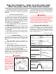
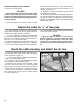
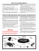
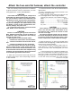
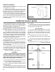
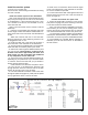

Figure 19
butt connector.
Attach the other end of the wire from the brake light
switch to the other end of the yellow butt connector.
8. Reinstall the brake light fuse.
Seal the firewall
1. If you had to drill a hole through the towed vehi-
cle’s firewall, cut the grommet (Figure 15) on one side,
and slide it over the nylon vacuum line, the monitor
harness and all of the electrical wiring from the con-
troller.
Fit the grommet into the hole in the firewall.
2. Completely seal the grommet with a silicone seal-
ant.
Note: failure to seal the grommet completely may
allow engine fumes and water into the passenger com-
partment.
3. Reattach the door trim, paneling or carpeting over
continued on next page
Install the monitor system
Install the monitor harness in the towed vehicle
1. Follow all of the steps in the owner's manual to
prepare the vehicle for towing (for example: neutral;
ignition switch position; pull fuses; etc.).
2. Apply the brakes and check to see if the brake lights
illuminate. If they do not, an optional stop light switch
kit must be installed — visit www.roadmasterinc.com.
Note: check the owner’s manual to see if the vehicle
has an “automatic shut down” feature. If so, an optional
stop light switch kit must be installed, as the brake light
switch will stop working at some point during towing.
3. Choose a mounting point at the front of the vehicle,
near the electrical socket, for the end of the 15-foot
harness with a female bullet connector.
Attach the connector with one or more wire ties;
allow enough slack so that a matching connector can
be plugged into and out of it.
4. Route the other end of the harness through the en-
gine compartment and through the hole in the firewall.
Use the same route as the break away wiring harness,
if that is convenient.
5. Locate the towed vehicle's brake light switch. With
a multi-meter, find the “cold” side of the switch. (The
cold side of the switch does not register voltage unless
the brakes are applied.)
Remove the vehicle’s brake light fuse.
CAUTION
Failure to remove the brake light fuse may cause
the vehicle’s theft deterrent system, or other elec-
trical system indicators, to be activated if the brake
pedal is depressed during the installation. This may
require non-warranty repair to the vehicle.
6. Cut the brake light wire, a few inches downstream
from the cold side of the brake light switch.
Note: if a Brake-Lite Relay is installed, the connec-
tion must be between the Brake-Lite Relay and the
brake light switch.
7. If necessary, trim the monitor wiring harness. Attach
the monitor wire and one end of the wire from the cold
side of the brake light switch to one side of a yellow
Attach the controller
continued from preceding page
flanges (Figure 18) is attached to the controller. Slide
the flange under the carpet.
Repeat for the remaining side; with a pair of pliers
bend this flange down 45º and slide it under the car-
pet. Press down on the controller above the flange to
straighten the flange and secure the controller.
6. You will test and adjust for proper braking pressure
in a later step. So leave the brake pressure adjustment
knob on the controller (page one) accessible — do not
reinstall any trim panels that would prevent adjusting
the brake pressure.
Figure 18
14