
Specifications


All specifications subject to change without notice
Tow bar rated
at 6,000 pounds
ROADMASTER, Inc. 6110 NE 127th Ave. Vancouver, WA 98682 800-669-9690 Fax 360-735-9300 www.roadmasterinc.com
852482-08 05/14
Owners and installers must read
the installation instructions
and carefully note the warnings!
Quick-disconnect parts list:
(2) quick-disconnects
(parts “A” and “B”)
(2) safety plates (“C”)
All mounting hardware
Installing the
‘quick-disconnect’ system
Figure 1
Figure 2
Falcon Installation Instructions
T
his tow bar is equipped with an exclusive “quick-disconnect” (or, “QD”)
system. Before connecting the tow bar to the vehicle, first install the
components of the QD system to the mounting bracket.
Note: the quick-disconnect system is not used with ROADMASTER
‘MS’ or ‘MX’ series mounting brackets. If the towed vehicle has MS or
MX brackets, proceed to “Connecting the tow bar.” The quick-disconnect
system should be reserved, however, for subsequent vehicles which may
not have these brackets.
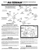
1. First, attach the quick-disconnects (“QDs,” parts “A” and “B” in Figure
1) to the tow bar mounting brackets. Attach the QDs so that the vertical
pin on each is pointing up, as shown in Figure 1.
Attach part “A” on the passenger side, and part “B” on the driver’s side.
Use the supplied ½" x 1¾" bolts, the two safety plates (parts “C”), and the
flat washers, lock washers and nuts, as shown in Figure 1.
Both QDs have an extra hole — “D” in Figure 1 — for safety cable attach-
ment. Mount parts “A” and “B” so that the “D” holes are to the outside.
Do not tighten any of the bolts — leave them loose for now — they will
be tightened later.
Use all mounting hardware and both safety plates. If all supplied
materials are not used, the quick-disconnects, the quick-disconnect
bases or other components may vibrate loose, which may cause prop-
erty damage, personal injury or even death.
2. Test-fit the crossbar — lower the crossbar (Figure 2) over the quick-
disconnects. The vertical pins at the top of both QDs should fit through
the top holes at the ends of the crossbar (Figure 2), and the vertical pins
at the bottom of the crossbar should fit through the lower holes on the
quick-disconnects (Figure 2).
3. The quick-disconnects must be positioned so that the tow bar is centered
on the front of the vehicle.
If necessary, adjust the quick-disconnects by moving them to the left
or the right, until the tow bar is centered to the front of the vehicle.
The quick-disconnects must be centered on the mounting brackets.
If they are attached too far to the left or the right, the tow bar will
not be centered on the towed vehicle, which will cause excessive tire
wear and other consequential, non-warranty damage.
4. Once the crossbar slides on and off easily, torque the four bolts to 75
ft./lbs.
Again, test-fit the crossbar over the QDs, to verify that the crossbar
slides on and off easily. If it does not, adjust the QDs again.
5. Insert the linch pins (Figure 2) through the upper holes in the vertical
pins on both QDs.
All linch pins must be locked. The rings are spring-loaded — they must
be snapped over the pins, with the curved side of the linch pin touching
the ring, in order to keep the QD bases secure.
Towing vibrations will force the linch pins out unless they are prop-
erly locked in place over the vertical pins on both quick-disconnects.
Failure to properly attach and lock all linch pins will result in the
loss of the towed vehicle, which may cause property damage, personal
injury or even death.