
User Manual

38
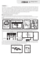
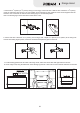
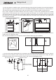
12. After installation, the range hood must be kept horizontal. In the end, insert the oil cup and power it for test run.
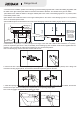
Min 29- (7 0mm)
1
Max 32- /2”(825 mm)
9
/16” 5
3
/8”
(10mm)
3
/8”
(10mm)
6 (152.4mm)
12”(304.8 mm)
”
●Installation without upper cabinet
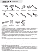
1. Open the container and take out the machine, and check
the items inside against the packing list.
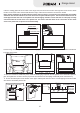
2. Open the duct hole at the top of the upper cabinet according
to the opening position and size as shown in the picture below.
3. Draw a vertical center line in the installation position, and
then use the beam detector to find the beam to fix the hitching leg, and mark it with a pencil.
Note: select the mainframe panel accessories if there is no
cabinet above the stove.
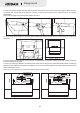
Min 28-
Max 31- ”
(795 mm)
3
/8”
(720mm)
5
/16
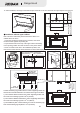
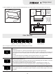
4. Determine the positions to fix the hitching leg and the hitching leg stop block.
2- ”
(55mm)
3
/16 2
(55mm)
3
- /16”
4- ”
(110mm)
5
/16
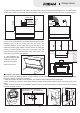
Hitching leg
stop block
mounting hole
4×60
wood screw
2-
(60±2mm)
3
/8”
Confirm the hitching leg position with the cooker supporting surface as
the base and mark the drill holes. The relevant size is given as below:
1) The minimum distance between the cooker supporting surface and
3
the center of the hitching leg hole is 28- /8 mm
2) The maximum distance between the cooker supporting surface and
5
the center of the hitching leg hole is 31- /16”(795mm);
3) The installment pitch of holes between the center of the hitching leg
3
hole and the hitching leg stop block is 2- /8”(60±2mm).
”(720 )
Duct diameter
Ø6”(Ø153mm)
Hole diameter
1
Ø6- /2”(Ø165mm)
Wall
1
6- /2”(Ø165mm)
Range Hood