COLORSPOT 170 AT Table of contents 1. Safety instructions ......................................................................................................... 3 2.Operating determinations .............................................................................................. 4 3.Description of the device ............................................................................................... 5 4.Installation .................................................................................
CAUTION! Keep this device away from rain and moisture! Unplug mains lead before opening the housing! FOR YOUR OWN SAFETY, PLEASE READ THIS USER MANUAL CAREFULLY BEFORE YOU INITIAL START - UP! 1. Safety instructions Caution ! Be careful with your operations.With a dangerous voltage you can suffer a dangerous electric shock when touching the wires This device has left our premises in absolutely perfect condition.
2.Operating determinations This device is a moving-head spot for creating decorative effects and was designed for indoor use only. This device is designed for professional use, e.g. on stages, in discotheques, theatres etc. Lighting effects are not designed for permanent operation. Consistent operation breaks will ensure that the device will serve you for a long time without defects. Never run the device without lamp! Do not shake the device. Avoid brute force when installing or operating the device.
3.
4.Installation 4.1Fitting/Exchanging the lamp DANGER ! Install the lamp with the device switched off only. Unplug from mains before ! Lamp socket assembly screws "X,Y,Z W" To insert the lamp (CDM-SA/T 150W/942): 1.Disconnect the fixture from power and allow it to cool. 2.Loosen the 4 screws „X, Y, Z,W” on the lamp socket assembly at the back of the head. 3.Gently pull the lamp socket assembly out of the head.Hold this assembly while replacing the lamp. 4.
If the light is brighter around the edge than it is in the center, or if light output is low, the lamp is too far back in the reflector. „Push” the lamp out by turning the screws „A, B, C” counterclockwise 1/4-turn at a time the light is bright and evenly distributed. 4.3 Inserting/Exchanging the colours and rotating gobos DANGER! Install the colours or gobos with the device switched off only.
CAUTION! Never unscrew the screws of the rotating gobo as the ball bearing will otherwise be opened! 4.4 Rigging DANGER TO LIFE! Please consider the respective national norms during the installation! Theinstallation must only be carried out by an authorized dealer! The installation of the projector has to be built and constructed in a way that it can hold 10 times the weight for 1 hour without any harming deformation. The installation must always be secured with a secondary safety attachment, e.g.
CAUTION! Use 2 appropriate clamps to rig the fixture on the truss. Follow the instructions mentioned at the bottom of the base. Make sure that the device is fixed properly! Ensure that the structure (truss) to which you are attaching the fixtures is secure. The moving-head can be placed directly on the stage floor or rigged in any orientation on a truss without altering its operation characteristics .
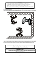
Fixation via the Omega holders 1. Screw the clamps (1) to the omega holders (4) through the hole in the holders. 2. Fasten the omega holders on the botton of the base by inserting both quick-lock fasteners (3) into the holes of the base and tighten fully clockwise. 3. Fasten the safety-rope (2) through the two apertures on the bottom of the base and over the trussing system. 1-Clamp 2-Safety-rope 3-Quick-lock fastener 4-Omega holder 4.
4.6 DMX- 512 connection, master/slave connection Controller operation Master/slave operation Only use a stereo shielded cable and 3-pin XLR-plugs and connectors in order to connect the controller with the fixture or one fixture with another.
5. DMX Protocol 16-bit 16-bit Mode 1 Mode 2 Channel Channel 1 2 3 4 5 Value 1 Pan Pan movement by 530° proportional 0-255 Tilt Tilt movement by 280° proportional 0-255 Pan fine Fine control of pan movement proportional 0-255 Tilt fine Fine control of tilt movement proportional 3 2 4 5 253-255 6 8 Speed of PAN/TILT movement Max. speed (tracking mode) From max. speed to min.speed (vector mode) Max. speed(track.mode),black-out while colour or gobo changes Max.
16-bit 16-bit Mode 1 Mode 2 Channel Channel 9 10 Value Gobo 4 Gobo 5 Gobo 6 Gobo 7 Gobo wheel rotation from slow to fast proportional proportional proportional proportional proportional 0-127 128-189 190-193 194-255 Rotating gobo rotation Gobo indexing Forwards gobo rotation from fast to slow No rotation Backwards gobo rotation from slow to fast proportional proportional step proportional 9 10 11 0-31 32-63 64-95 96-127 128-159 160-191 192-223 224-255 12 Type of control 156-175 176-195 196-2
8-bit 16-bit Mode 3 Mode 4 Channel Channel 1 2 Value Function 0-255 Pan Pan movement by 530° proportional 0-255 Tilt Tilt movement by 280° proportional 0-255 Pan fine Fine control of pan movement proportional 0-255 Tilt fine Fine control of tilt movement proportional 1 2 3 4 3 5 0 1-249 250-252 253-255 4 6 0-127 128-139 140-229 230-239 240-255 5 7 0 11 23 35 46 58 70 81 93 105 116 128-189 190-193 194-255 6 Speed of PAN/TILT movement Max. speed (tracking mode) From max.
8-bit 16-bit Mode 3 Mode 4 Channel Channel 7 Value Shaking gobos with variable speed Gobo 1 Gobo 2 Gobo 3 Gobo 4 Gobo 5 Gobo 6 Gobo 7 Gobo wheel rotation from slow to fast proportional proportional proportional proportional proportional proportional proportional proportional 0-127 128-189 190-193 194-255 Rotating gobo rotation Gobo indexing Forwards gobo rotation from fast to slow No rotation Backwards gobo rotation from slow to fast proportional proportional step proportional 12 No function 14
The COLORSPOT 170 AT can be operated with a controller in controller mode or without the controller in standalone mode. Both modes are described in the texts below. 6.Controller mode The fixtures are individually addressed (001-497) on a data link and connected to the controller.The fixtures respond to the DMX signal from the controller. 6.
Focus Motorized focus enables the beam to be focused anywhere on the stage. Shutter/Dimmer/Strobe The dimming (0-100%) is provided by the simple mechanical shutter unit. This unit may also be used for strobe effect (1 - 8 flashes per second). 7. Stand - alone mode The fixtures on a data link are not connected to the controller but can execute pre-set programs which can be different for every fixture.To set the program to be played,see the "Stand-alone setting" ( menu "St.AL.").
8. Functions of the control panel The control panel situated on the front side of the base offers several features. You can simply set the DMX address,master/slave mode, read the number of lamp or unit hours, run test, make a reset and also use many functions for setting and service purposes. The main menu of the control panel is accessed by pressing the [ Mode ] button - press this one so many times until the display shows message "A001" (with actually stored address).
Note:Disconect the fixtures from the DMX controller before master/slave operating ,otherwise data collisions can occur and the fixtures will not work properly! If the fixture is set as the master and DMX signal is connected to its input,the error massage "MAEr" will appear on its display and the fixture's address will be set to its DMX address in order to respond to DMX signal from the controller. For example: The master fixture has this address setting:"dM.Ad."-menu.........A013 "MA.SL."-menu........
- The number of the hours that the COLORSPOT 170 AT has been powered on since the counter was last reset.Press [Enter] or [Mode ] to return to the menu.In order to reset this counter to 0, you have to hold the [ Up ] and [ Down ]-button and press the [ Enter]-button. Lamp On time - This option enables you to read the total number of the operation hours with the lamp on since the COLORSPOT 170 AT has been fabricated.Press [Enter ] or [ Mode ] to return to the menu.
- Pan reverse This function allows you to invert the pan movement. Use the [ Up ] or [ Down ] buttons to select "On" if you wish this feature or "Off" if you don’t wish this feature and press [Enter ] to confirm or [ Mode ] to cancel and return to the menu. - Tilt reverse This function allows you to invert the tilt movement.
Lamp presetting This function allows you to adjust the lamp settings: Lamp On after switching the fixture On This function enables to turn the lamp on automatically after switching the fixture on. Use the [ Up] and [Down] buttons to select "On" if you wish to turn the lamp on automatically after switching the fixture on or "Off" if you wish the lamp off after switching on the fixture and press [Enter] to confirm or [ Mode] to cancel and return to the menu.
- Display -intensity With this function you can adjust the display intensity from 20% to 100% . Use the [Up ] or [Down ] buttons to select the level of the display intensity and press [ Enter ] to confirm or [ Mode ] to cancel and return to the menu. - Display-reverse With this function, you can rotate the display by 180°. Use the [ Up ] or [ Down ] buttons to select "normal display" or "display turned by 180°" and press [ Enter ] to confirm or [ Mode ] to cancel and return to the menu.
- Default settings Press [ Enter ] to reset all fixture personalities (not the adjusting functions) to the default values. On the display will appear "rSt" meaning that the fixture makes the reset. See the table of personality setting and their default positions. Personality Display Default values (SHADED) Pan reverse Tilt reverse DMX presetting Lamp On after switch. the fixture On Lamp Off via DMX Lamp On if DMX is present Lamp Off if DMX is missing Blackout during mov.
8.6 Test sequences This function allows you to run a special demo-test sequences without an external controller, which will show you some possibilities of using COLORSPOT 170 AT. Press [ Up ] or [ Down] keys to select the "Mod1" or "Mod2" sequences. The "Mod1" is suitable for projections on the wall, ceiling or ground without any head-movement, the "Mod2" uses all COLORSPOT 170 AT functions and therefore is good for a complete introduction of the fixture.
the fixture On.Use the [ Up ] or [ Down ] buttons to select desired program ("tESt"- bilt-in program) or "OFF" if you don't want trigger any program after switching the fixture On and press [ Enter ] to confirm or [ Mode ] to cancel and return to the menu.Selected program will be played continuously in a loop as long as it appears on the display. This option should be set "OFF" for all slaves in the master/slave chain by reason of the right program starts. For example: You have selected program "PrG.
8.8 Reset function Press [ Enter ] button to run a reset. This option enables the COLORSPOT 170 AT to index all effects (functions) and return to their standard positions. 8.9 Special functions Use the [ Up ] or [ Down ] buttons to browse through the special functions and select the one by pressing [ Enter ]-button. - Manual control of effects The function allows you to control manually the channel functions of the fixture.
-- Fixture code The option contains identification code (1-9999) for the fixture, which is used for the master/slave operation. - Adjusting the default positions of the colour and gobo wheels By this function you can calibrate and adjust the colour and gobo wheels to their standard/right positions.
PCB). The color-wheel is not located in the default position after the reset. r.G.Er. (Rotating gobo-wheel error) This message will appear after the reset of the fixture if the magnetic-indexing circuit malfunctions (sensor failed or magnet missing) or the stepping-motor is defective (or its driver circuit on the main PCB). The rotating gobo-wheel is not located in the default position after the reset. i.G.Er.
Beampath: Colour-wheel - 10 dichroic-filters plus white - Colour-wheel with variable rotation speed - All colours are easily replaceable Rotating gobos-wheel - 3 metal gobos, 3 glass gobos and 1 dichroic gobo rotating in both directions at different speeds - Gobo indexing - Rotating gobo-wheel cont. rotation -Metal gobos:outside diameter=26.9mm,image diameter=22.5mm,aluminium,thickness=0.5mm -Multicolor dichroic gobo:outside diameter=26.8mm,thickness=1.
Channel 8 9 10 11 12 13 14 15 16 Mode 1 (default) R.gobos Gobo rotation Focus Shutter,strobe Dimmer Mode 2 R.gobos Gobo rotation Focus Shutter,strobe Dimmer Pan/Tilt: -Pan movement range 530° -Tilt movement range 280° -Automatic Pan / Tilt position correction -Maximum PAN-movement 530° in 2,2 s -Maximum TILT-movement 280° in 1.
Accessories: gobo-set 8...................................................15050017 omega holder (2 pieces)................................99010261 11. Maintenance and cleaning The operator has to make sure that safety-relating and machine-technical installations are inspected by an expert after every four years in the course of an acceptance test. The operator has to make sure that safety-relating and machine-technical installations are inspected by a skilled person once a year.
12. Appendix 1 - Menu map Menu Level 1 A001 SL.Ct. Menu Level 2 dM.Ad. MA.SL. SL.C.1SL.C.9 Po.ti. La.ti. LA.St. InFo dM.In. VErS r.PAN r.tilt dM.Pr. Menu Level 3 A001A497 d.Abl. MASt. SLA.1SLA9 totl rSEt totl rSEt totl rSEt Pan tilt F.Pan F.tilt SPEd Func. Colo. r.Gob. G.rot. Foc. Stro. dimr On OFF On OFF Mod.1 Mod.2 Mod.3 Mod.4 LA.Au. LA.Pr. d.L.OF. dM.On dM.OF. PErS EN.Sn. On OFF turn diSp. d.On d.Int. bL.Co FEEd. Mi.SE. dF.SE. On OFF On OFF 1..10..
Menu Level 1 LAMP tESt Menu Level 2 On OFF Mod.1 Mod.2 Audi Auto PLAy St.Al. Edit rESE Menu Level 3 Pan tilt Go run On OFF OFF tESt PrG.1 PrG.2 PrG.3 tESt PrG.1 PrG.2 PrG.3 PrG.1PrG.3 PAn tilt SPEd Colo. SPEC. Manu. r.Gob. G.rot Foc. Stro. dimr LAAd Pan tilt Foc. Menu Level 4 Menu Level 5 Menu Level 6 0-255 0-255 run run run run run P.End Pan tilt F.Pan F.tilt MASt.SPEd SLA.9 Colo. (only if r.Gob. Master is G.rot. selected) Foc. Stro. dimr S.
Menu Level 1 SPEC. (cont.) Menu Level 2 Code AdJ. Menu Level 3 Pan tilt F.Pan F.tilt SPEd Func. Colo. r.Gob. G.rot. Foc. Stro. dimr F.CAL Menu Level 4 0-255 0-255 0-255 0-255 0-255 0-255 0-255 0-255 0-255 0-255 0-255 0-255 Colo. r.Gob. A.
13. Appendix 2 - Changing the power supply settings Both the transformer and the ballast must be connected correctly for the local AC voltage and frequency. The wrong settings can cause poor performance or demage of the moving head.The factory settings are printed next to the power switch. If you want to change the power supply settings,follow the instructions: 1.Disconnect the fixture from AC power. 2.Remove the base cover by loosening the 3 screws. 3.