Version 2.
DigitalSpot 5000 DT Table of contents 1. Safety instructions ......................................................................................................... 4 2.Operating determinations............................................................................................... 5 3. Introduction..................................................................................................................... 5 4. Description of the device........................................................
21.2 Picture merging example ...................................................................................... 62 23. Effect synchronization ............................................................................................... 63 24. Remote configuration via the WWW browser.......................................................... 64 25. Technical specifications ............................................................................................ 65 26. Maintenance ....................
CAUTION! Keep this device away from rain and moisture! Unplug mains lead before opening the housing! FOR YOUR OWN SAFETY, PLEASE READ THIS USER MANUAL CAREFULLY BEFORE YOU INITIAL START - UP! 1. Safety instructions Every person involved with installation and maintenance of this device have to: - be qualilfied - follow the instructions of this manual CAUTION! Be careful with your operations.
2.Operating determinations If the device has been exposed to drastic temperature fluctuation (e.g. after transportation), do not switch it on immediately. The arising condensation water might damage your device. Leave the device switched off until it has reached room temperature. Do not shake the device. Avoid brute force when installing or operating the device. When choosing the installation-spot, please make sure that the device is not exposed to extreme heat, moisture or dust.
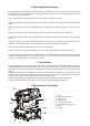
The head can be locked for transportation- the tilt lock button (5) is pushed and the pan lock/unlock lever (2) is in lock position. To unlock the head, press the tilt unlock button (6) and move the pan lock/unlock lever to unlock position. Front panel 1 - Display 2 - RNS control wheel 3 - Escape button 4 - Enter button Rear panel 1 - Power cord 2 - Power switch 3 - Fuse 4 - 5-pin DMX outputt 5 - 5-pin DMX input 6 - Ethernet input 7 - USB inputs 8 - 15-Pin VGA intput-dataprojec.
5. Powering on the DigitalSpot 5000 DT To power on the fixture,simply connect it to the AC mains supply (the power switch on the rear side of the fixture has to be in "On" position). 6. Shutting down the DigitalSpot 5000 DT There are two recommended ways to shutdown the fixture: 1.A DMX controller can switch off the projector lamp and shut down the fixture with the "Lamp Off,Fixture Off" option on the control channel 8 (see DMX protocol). 2.
. Rigging the fixture Please consider the respective national norms during the installation! The installation must only be carried out by an authorized dealer! The installation of the fixture has to be built and constructed in a way that it can hold 10 times the weight for 1 hour without any harming deformation. The installation must always be secured with a secondary safety attachment, e.g. an appropriate catch net.
Fixation via the omega holders 1. Bolt each clamp (1) to the omega holder (4) with M12 bolt and lock nut through the hole in the holder. 2. Fasten the omega holders on the bottom of the base by inserting both quick-lock fasteners (3) into the holes of the base and tighten fully clockwise. 3. Fasten the safety-rope (2) through the two apertures on the bottom of the base and over the trussing system.
9. DMX-512 connection The fixture is equipped with both 3-pin and 5-pin XLR sockets for DMX input and output.The sockets are wired in parallel. Only use a shielded twisted-pair cable designed for RS-485 and 3-pin or 5-pin XLR-plugs and connectors in order to connect the controller with the fixture or one fixture with another.
10. Ethernet connection The fixtures on a data link are connected to the Ethernet with Art-Net communication protocol.The controlling software from PC (or lighting console) has to support Art-Net protocol. Art-Net communication protocol is based on the TCP/IP.Its purpose is to allow transfer of large amounts of DMX 512 data over a wide area using standard network technology. An IP address is the Internet protocol address.The IP uniquely identifies any node (fixture) on a network.
11. DigitalSpot 5000 DT - DMX Protocol - version 3.5 Channel 1 2 3 4 Value Pan Pan movement by 530° proportional 0 - 255 Pan Fine Fine control of pan movement proportional 0 - 255 Tilt Tilt movement by 280° proportional 0 - 255 Tilt fine Fine control of tilt movement proportional 1 - 255 7 step Time from 0.1 s to 25.5 s.
Channel 10 11 12 13 14 15 16 17 18 19 20 Value Function Type of control 0-255 Zoom Zoom from min. to max. (128-default) proportional 0-255 Focus Continuous adjustment from far to near (128-default) proportional 0 0-255 Analog Iris Open From max. diameter to min.
Channel 29 30 31 32 33 Value Function 0 1 2 3 4 5 6 7 8 9 10-255 Gobo control Play forward if dimmer (on layer 1) > 0, looping continuously Play forward if dimmer (on layer 1) > 0, hold on last frame Pause Play forward in continuous loop Play forward once and hold on the last frame No function Scrub (Display) the selected In Frame Scrub (Display) the selected Out Frame No function No function Reserved 0 1-127 128 129-255 Playback Speed Normal Speed Slow speeds from slowest ---> normal Normal Spee
Channel Value 33 34 35 36 37 38 39 40 41 42 43 44 45 46 47 48 49 50 51 52 53 54 55 56 57 58 59 60 61 62 63 64 65 66 67 68 69 70 71 72 73 74 75 76 77 78-79 Squeeze in Squeeze out Bend X Bend Y Tile frame Frame Plane flip X Plane flip Y Plane flip XY Plane mirror X top Plane mirror X bottom Plane mirror Y left Plane mirror Y right Plane mirror XY segment 1 Plane mirror XY segment 2 Plane mirror XY segment 3 Plane mirror XY segment 4 Plane tile 2x Plane tile 3x Plane tile 4x Plane tile 5x Plane cross tile
Channel Value 35 5 6 7 8 9 10 11 12 13 14 15 16 17 18 19 20 21 22 23 24 25 26 27 28 29 30 31 32 33-39 40 41 42 43 44 45-255 Black Mask Black Mask inverse Contrast Brightness RGB to GBR RGB to BRG RGB to RBG Black and white to black and white inverse timed Colour to black and white timed Colour to inverse timed Cycle Cycle inverse Reserved Reserved Colour Key Colour Key inverse Key Black Key Black inverse Key White Key White inverse White flash Black flash Alpha flash Invert flash BW flash Black and whit
Channel 45 46 Value 0-127 128 129-255 0-255 Function Type of control Gobo zoom Y coarse Narrowing Centre (128-default) Widening proportional step proportional Gobo zoom Y fine Zoom Y fine proportional 17
Gobo layer 2 Channel 47 48 Value 0-255 0-20 21-240 241-250 251 252-255 0 1-255 49 0 1-20 21-40 41-60 61-80 81-100 101-120 121-255 Function Dimmer Dimmer intensity from 0% to 100% (255-default) Gobo Folder selection Factory folders User folders Reserved Live input (capture card)-see channel 49 Reserved Gobo selection White 255 Gobos (one by one) If Live input (251 DMX) is selected on channel 48: White screen Video composite input-PAL system SVIDEO input- PAL system Video composite input-NTSC system SVID
Channel 58 58 Value Function Type of control Type of effect control 0 1 2 3 4 5 6 7 8 9 Gobo effect 1 Selection No effect Zoom sinus Zoom bump in fade out Zoom fade in bump out Reserved Zoom in fade Zoom out fade Scale xy sinus Reserved Reserved 10 11 12 13 14 15 16 17 18 19 20 21 22 23 24 25 26 27 28 29 30 31 32 33 34 35 36 37 38 39 40 41 42 43 44 45 46 47 48 49 50 51 52 53 54 55 56 57 Reserved XY pos. circle counter-clockwise XY pos. circle clockwise XY pos. scroll up XY pos. scroll down XY pos.
Channel Value 58 58 59 60 61 62 63 64 65 66 67 68 69 70 71 72 73 59 60 Function Type of control Plane cross tile 3x inverse Plane cross tile 4x Plane cross tile 4x inverse Plane cross tile 5x Plane cross tile 5x inverse Plane cross tiler 5x Plane cross tiler 5x inverse Plane bar Plane bar inverse Plane bar left-righ Plane bar top-bottom Reserved Reserved Gobo disc Gobo disc flip X Gobo disc flip Y none none none none none none none none none none none 74 75 76 77 78-79 80 81 82 83 84 85 86 87-255
Channel Value 60 28 29 30 31 32 33-39 40 41 42 43 44 45-255 Invert flash BW flash Black and white to black and white inverse Flash Gradient Wipe X Gradient Wipe Y Reserved Gaussian filter Mean filter Laplacian filter Emboss filter Sharpness filter Reserved 0-255 Gobo effect 2 control Control of amount/speed 61 Function 62 Reserved 63 Reserved 64 65 66 67 68 69 70 71 Type of control speed speed speed speed speed amount amount amount amount amount proportional Gobo Position X coarse Mov
Channel 77 78 79 80 81 82 83 84 85 86 Value Function Type of control Strobe Open light output Strobe-effect from slow to fast Open light output Random strobe-effect from slow to fast Open light output Iris displays current gobo from gobo layer 1 Iris displays current gobo from gobo layer 2 Reserved step proportional step proportional step step step step 0-255 Banner left positioning Positioning from left to right (0-default) proportional 0-255 Banner left rotation Rotation +/- 45° (128-default)
12. DigitalSpot 5000 DT - DMX Protocol - version 4.3 Channel 1 2 3 4 Value Pan Pan movement by 530° proportional 0 - 255 Pan Fine Fine control of pan movement proportional 0 - 255 Tilt Tilt movement by 280° proportional 0 - 255 Tilt fine Fine control of tilt movement proportional 1 - 255 7 step Time from 0,1 s to 25,5 s.
Channel 10 11 12 13 14 15 16 17 18 19 20 Value Function Type of control 0-255 Zoom Zoom from min. to max. (128-default) proportional 0-255 Focus Continuous adjustment from far to near (128-default) proportional 0 0-255 Analog Iris Open From max. diameter to min.
Channel 29 30 31 32 33 Value Function 0 1 2 3 4 5 6 7 8 9 10-255 Gobo control Play forward if dimmer (on layer 1) > 0, looping continuously Play forward if dimmer (on layer 1) > 0, hold on last frame Pause Play forward in continuous loop Play forward once and hold on the last frame No function Scrub (Display) the selected In Frame Scrub (Display) the selected Out Frame No function No function Reserved 0 1-127 128 129-255 Playback Speed Normal Speed Slow speeds from slowest ---> normal Normal Spee
Channel Value 33 34 35 36 37 38 39 40 41 42 43 44 45 46 47 48 49 50 51 52 53 54 55 56 57 58 59 60 61 62 63 64 65 66 67 68 69 70 71 72 73 74 75 76 77 78-79 Squeeze in Squeeze out Bend X Bend Y Tile frame Frame Plane flip X Plane flip Y Plane flip XY Plane mirror X top Plane mirror X bottom Plane mirror Y left Plane mirror Y right Plane mirror XY segment 1 Plane mirror XY segment 2 Plane mirror XY segment 3 Plane mirror XY segment 4 Plane tile 2x Plane tile 3x Plane tile 4x Plane tile 5x Plane cross tile
Channel Value 35 5 6 7 8 9 10 11 12 13 14 15 16 17 18 19 20 21 22 23 24 25 26 27 28 29 30 31 32 33-39 40 41 42 43 44 45-255 Black Mask Black Mask inverse Contrast Brightness RGB to GBR RGB to BRG RGB to RBG Black and white to black and white inverse timed Colour to black and white timed Colour to inverse timed Cycle Cycle inverse Reserved Reserved Colour Key Colour Key inverse Key Black Key Black inverse Key White Key White inverse White flash Black flash Alpha flash Invert flash BW flash Black and whit
Channel 45 46 Value 0-127 128 129-255 0-255 Function Type of control Gobo zoom Y coarse Narrowing Centre (128-default) Widening proportional step proportional Gobo zoom Y fine Zoom Y fine proportional 28
Gobo layer 2 Channel 47 48 Value 0-255 0-20 21-240 241-250 251 252-255 0 1-255 49 0 1-20 21-40 41-60 61-80 81-100 101-120 121-255 Function Dimmer Dimmer intensity from 0% to 100% (255-default) Gobo Folder selection Factory folders User folders Reserved Live input (capture card)-see channel 49 Reserved Gobo selection White 255 Gobos (one by one) If Live input (251 DMX) is selected on channel 48: White screen Video composite input-PAL system SVIDEO input- PAL system Video composite input-NTSC system SVID
Channel 58 58 Value Function Type of control Type of effect control 0 1 2 3 4 5 6 7 8 9 Gobo effect 1 Selection No effect Zoom sinus Zoom bump in fade out Zoom fade in bump out Reserved Zoom in fade Zoom out fade Scale xy sinus Reserved Reserved 10 11 12 13 14 15 16 17 18 19 20 21 22 23 24 25 26 27 28 29 30 31 32 33 34 35 36 37 38 39 40 41 42 43 44 45 46 47 48 49 50 51 52 53 54 55 56 57 Reserved XY pos. circle counter-clockwise XY pos. circle clockwise XY pos. scroll up XY pos. scroll down XY pos.
Channel Value 58 58 59 60 61 62 63 64 65 66 67 68 69 70 71 72 73 59 60 Function Type of control Plane cross tile 3x inverse Plane cross tile 4x Plane cross tile 4x inverse Plane cross tile 5x Plane cross tile 5x inverse Plane cross tiler 5x Plane cross tiler 5x inverse Plane bar Plane bar inverse Plane bar left-righ Plane bar top-bottom Reserved Reserved Gobo disc Gobo disc flip X Gobo disc flip Y none none none none none none none none none none none 74 75 76 77 78-79 80 81 82 83 84 85 86 87-255
Channel Value 60 28 29 30 31 32 33-39 40 41 42 43 44 45-255 Invert flash BW flash Black and white to black and white inverse Flash Gradient Wipe X Gradient Wipe Y Reserved Gaussian filter Mean filter Laplacian filter Emboss filter Sharpness filter Reserved 0-255 Gobo effect 2 control Control of amount/speed 61 Function 62 Reserved 63 Reserved 64 65 66 67 68 69 70 71 Type of control speed speed speed speed speed amount amount amount amount amount proportional Gobo Position X coarse Mov
Channel Value 75 9 10 11 12 13 : 255 76 77 78 79 80 81 82 83 84 85 86 87 Function 9500 K 9000 K 8600 K (every next value is by 25 K lower than previous) 8575 K 8550 K : 2500 K Type of control step step step step step : step 0 1-254 255 Digital Iris Open iris From max.diameter to min.
13. DigitalSpot 5000 DT - DMX Protocol - version 5.1 Channel 1 2 3 4 Value Pan Pan movement by 530° proportional 0 - 255 Pan Fine Fine control of pan movement proportional 0 - 255 Tilt Tilt movement by 280° proportional 0 - 255 Tilt fine Fine control of tilt movement proportional 1 - 255 7 step Time from 0.1 s to 25.5 s.
Channel 10 11 12 13 14 15 16 17 18 19 20 21 22 Value Function Type of control 0-255 Zoom Zoom from min. to max. (128-default) proportional 0-255 Focus Continuous adjustment from far to near (128-default) proportional 0 0-255 Analog Iris Open From max. diameter to min.
Channel Value Function Type of control 27 0-255 In Frame Low Defines the beginning of a media file segment as a percentage of the movie length (0-default) proportional 28 0-255 Out Frame High Defines the end of a media file segment as a percentage of the movie length (255-default) proportional 29 0-255 Out Frame Low Defines the beginning of a media file segment as a percentage of the movie length (255-default) proportional 30 31 32 33 34 0 1 2 3 4 5 6 7 8 9 10-255 Gobo control Play for
Channel Value 34 24 25 26 27 28 29 30 31 32 33 34 35 36 37 38 39 40 41 42 43 44 45 46 47 48 49 50 51 52 53 54 55 56 57 58 59 60 61 62 63 64 65 66 67 68 69 70 71 72 73 74 75 76 77 78-79 80 81 82 83 84 Function XY inv. rotate X inv. y rotate Tile xy Tile xy XYZ rot. cube XYZ rot. sphere X rot. cylinder Y rot.
Channel 34 35 36 36 37 Value Function 85 86 87-255 Plane mirror X-inverse,Y Plane mirror X,Y-inverse Reserved 0 - 255 Gobo effect 1 control Control of amount/speed 0 1 2 3 4 Black Mask Black Mask inverse Contrast Brightness RGB to GBR RGB to BRG RGB to RBG Black and white to black and white inverse timed Colour to black and white timed Colour to inverse timed Cycle Cycle inverse Reserved Reserved Colour Key Colour Key inverse Key Black Key Black inverse Key White Key White inverse White flash Bla
Channel 42 43 44 45 46 47 48 Value Function Type of control Gobo position Y coarse Movement down Centre (128-default) Movement up proportional step proportional 0-255 Gobo position Y fine Position Y fine proportional 0-127 128 129-255 Gobo zoom X coarse Narrowing Centre (128-default) Widening proportional step proportional Gobo zoom X fine Zoom X fine proportional Gobo zoom Y coarse Narrowing Centre (128-default) Widening proportional step proportional 0-255 Gobo zoom Y fine Zoom Y fin
Gobo layer 2 Channel 49 50 Value 0-255 0-20 21-240 241-250 251 252-255 0 1-255 51 0 1-20 21-40 41-60 61-80 81-100 101-120 121-255 Function Dimmer Dimmer intensity from 0% to 100% (255-default) Gobo Folder selection Factory folders User folders Reserved Live input (capture card)-see channel 49 Reserved Gobo selection White 255 Gobos (one by one) If Live input (251 DMX) is selected on channel 48: White screen Video composite input-PAL system SVIDEO input- PAL system Video composite input-NTSC system SVID
Channel 60 Value Function Type of control Type of effect control 0 1 2 3 4 5 6 7 8 9 Gobo effect 1 Selection No effect Zoom sinus Zoom bump in fade out Zoom fade in bump out Reserved Zoom in fade Zoom out fade Scale xy sinus Reserved Reserved 10 11 12 13 14 15 16 17 18 19 20 21 22 23 24 25 26 27 28 29 30 31 32 33 34 35 36 37 38 39 40 41 42 43 44 45 46 47 48 49 50 51 52 53 54 55 56 57 Reserved XY pos. circle counter-clockwise XY pos. circle clockwise XY pos. scroll up XY pos. scroll down XY pos.
Channel Value 60 58 59 60 61 62 63 64 65 66 67 68 69 70 71 72 73 61 62 Function Type of control Plane cross tile 3x inverse Plane cross tile 4x Plane cross tile 4x inverse Plane cross tile 5x Plane cross tile 5x inverse Plane cross tiler 5x Plane cross tiler 5x inverse Plane bar Plane bar inverse Plane bar left-righ Plane bar top-bottom Reserved Reserved Gobo disc Gobo disc flip X Gobo disc flip Y none none none none none none none none none none none 74 75 76 77 78-79 80 81 82 83 84 85 86 87-255
Channel Value 62 28 29 30 31 32 33-39 40 41 42 43 44 45-255 Invert flash BW flash Black and white to black and white inverse Flash Gradient Wipe X Gradient Wipe Y Reserved Gaussian filter Mean filter Laplacian filter Emboss filter Sharpness filter Reserved 0-255 Gobo effect 2 control Control of amount/speed 63 Function 64 Reserved 65 Reserved 66 67 68 69 70 71 72 73 74 Type of control speed speed speed speed speed amount amount amount amount amount proportional Gobo Position X coarse
Channel Value 78 6 7 8 9 10 11 12 13 : 255 11000 K 10500 K 10000 K 9500 K 9000 K 8600 K (every next value is by 25 K lower than previous) 8575 K 8550 K : 2500 K step step step step step step step step : step 0 1 2 3 4 5 6 7 8 9 10 11 12 13 14 15 16 17 18 19 20 21 22 23 24 25 26 27 27 29 30 31 32 33 34 35 36 37 38 39 40 41 42 43 44 45 46 47 48 49 Digital Iris - type selection Circular ,outside-->in,sharp edge Circular ,outside-->in,fuzzy edge 1 Circular ,outside-->in,fuzzy edge 2 Circular ,outside-->i
Channel Value Function 79 50 51 52 53 54 55 56 57 58 59 60 61 62 63 64 65 66 67 68 69 70 71 72 73 74 75 76 77 78 79 80 81 82 83 84 85 86 87 88 89 90 91 92 93 94 95 96 97 98 99 100 Radial wipe ,left -->bottom,sharp edge Radial wipe ,left -->bottom,fuzzy edge 1 Radial wipe ,left -->bottom,fuzzy edge 2 Radial wipe ,left -->bottom,fuzzy edge 3 Radial wipe ,left -->bottom,fuzzy edge 4 (maximum) Radial wipe ,bottom-->left,sharp edge Radial wipe ,bottom-->left,fuzzy edge 1 Radial wipe ,bottom-->left,fuzzy edg
Channel Value 79 110 111 112 113 114 115 116 117 118 119 120 121 122 123 124 125 126 127 128 129 130 131 132 133 134 135 136 137 138 139 140 141 142 143 144 145 146 147 148 149 150 151 152 153 154 155 156 157 158 159 160 161-255 80 81 Function Horizontal bands 8x,top-->bottom Horizontal bands 8x,bottom-->top Vertical bands 8x,left-->right Vertical bands 8x,right-->left Horizontal bands 16x,top-->bottom Horizontal bands 16x,bottom-->top Vertical bands 16x,left-->right Vertical bands 16x,right-->left Ho
Channel 82 83 84 85 86 87 88 89 90 91 92 93 Value step proportional step proportional step step step step 0-255 Banner left positioning Positioning from left to right (0-default) proportional 0-255 Banner left rotation Rotation +/- 45° (128-default) proportional 0-255 Banner right positioning Positioning from right to left (0-default) proportional 0-255 Banner right rotation Rotation +/- 45° (128-default) proportional 0-255 Banner top positioning Positioning from top to bottom (0-default
14.DigitalSpot 5000 DT - Control menu map Default settings=Bold print Fixture Address DMX Settings Artnet Settings Set DMX Address Activate DMX Mode Set IP Address Custom IP Address Default IP Address Set ArtNet Universe (0 -15) Set ArtNet Subnet (0 -15) Activate ArtNet Mode Fixture information DMX Values Pan (0-255) : Banner rotation (0-255) Software Version Graphic Engine IC1 Motherboard IC2 Motherboard IC3 Motherboard Headboard Product IDs Mac Addr.
Lamp On/Off (On,Off) Manual Control Manual DMX Control Pan (0-255) : Banner Rotation (0-255) Video Input Selection Internal Input External VGA Input External SVIDEO Input Data projector Control Stand-alone setting Playing Program Test Program In Loop Program 1 In Loop : Program 10 In Loop Editing Program Program 1 : Program 10 Edit Steps Normal Static Step1 : Step 99 Start Step (1-99) End Step (1-99) Preview Mode Reset functions Reset Pan/Tilt System Reset Zoom/Focus system Reset Iris system Rese
Air Filters Maximum Nonresetable Projector temp.1 [°C] Projector temp.2 [°C] Projector temp.3 [°C] Pan/Tilt Board [°C] Maximum Resetable Projector temp.1 [°C] Projector temp.2 [°C] Projector temp.3 [°C] Pan/Tilt Board [°C] Time To Clea Up Filters Set Clean Up Timer (10 hours..50 hours ..300 hours) Special functions Regenerate Thumbnails Set Thumbnail size (50..96...
15. Operating modes Before operating the DigitalSpot 5000 DT from a DMX 512 controller,you need to define the source of DMX data,which may be: DMX 512 - data is transmitted over standard DMX cables.Set a valid DMX start address,which is defined as the first channel from which the DigitalSpot 5000 DT will respond to the controller. If you set, for example, the start address to channel 1, the DigitalSpot 5000 DT will use channels from 1 to 86 for control.
Set ArtNet Universe - Select this submenu to set a Universe (0-15). The Universe is a single DMX 512 frame of 512 channels. Set ArtNet Subnet - Select the option to set Ethernet subnetworks to which the fixture belongs (0-15) After setting all Artnet parametres confirm setting by using the function "Activate Artnet Mode": Activate Artnet Mode - Data is received from Ethernet input. 16.2 Fixture information DMX Values --- Select this function to read DMX values of each channel received by the fixture.
Active Blackout while: --- Use this function if you wish to close the light output during certain events: During Movement correction --- Select this function to enable the blackout during the head movement correction (if the moving head lost its right pan/tilt position for a short moment). Pan/Tilt Moving --- This function closes the light output during pan/tilt changes.
ground without any head movement.By means of items Pan,Tilt,Zoom and Focus is possible to adjust moving head to desired position. Running program is possible to pause by pressing [ENTER] . Editing Program --- Select this menu to edit or create the program.The DigitalSpot 5000 DT has 10 freely-programmable programs,each up to 99 steps.Each program step has a step time,during which effects last in a current step. Procedure: 1. Select the program you want to edit (“Program 1” - “Program 10”) and press [ENTER].
cleaning air filters.Expired time period is signalized by a negative mark at the time value and a warning icon (triangle) on the display with the following message: "Please , Clean Up Airs Filters." Clean the filters and reset this menu item (by pressing "Enter" button twice while this menu is highlighted) Set Cleanup Timmer - Cleaning schedule for the fixture depends on the operating enviroment.It is therefore imposible to specify accurate cleaning interval.
To download folder from the Media folder to the USB stick. 1.Insert the USB stick to the USB port , select "USB Data Synchronize" from the menu and press Enter.There is "USB1" or "USB2" (depends on used USB port) displayed on the screen. 2.Press Enter,select Open,press Enter. 3.Select "Media",press Enter, 4.If you want to copy whole Media folder from the fixture (including subfolders 000-240),select item "Sychronize from Fixture".If you want to copy only one subfolder (e.g.
17.Media content management As you seen earlier in chapter "7. Folders organization",the DigitalSpot 5000 DT use the root folder named "Media".This folder contains subfolders (000,001...240) and inside each subfolder is the collection of media that the subfolder holds.The files in subfolders are alphabetized and associated with DMX values.The first part of the file name should be a a 3-digit number followed by an underscore and a name e.g.: 001_sun..................... 1 DMX 002_snow_castle........
If all settings are correct,you will see "Media" and "Update" folders in Windows explorer window and now you can work with them as with local folders and files. The second way, how to add or remove files from the subfolders is by means of USB stick-see "USB Data Synchronization" in chapter "16.10 Special function. " 18.Keystones If an image is output from the DigitalSpot 5000 DT at an angle the image may be skewed.Eight keystones adjust the image shape.
use channel 21(KeyStone X-ratio) for correction use channel 22 (KeyStone Y-ratio) for correction 19.In Frame and Out Frame parametres You can select any segment of a video file for playback by assigning parametres for In Frame (start point) and an Out Frame (end point) as pictured below. The In Frame parameter corresponds to a 16-bit DMX value equal to a starting point for the playback segment of the selected video file.
4 Play forward once Plays the video segment from In Frame point to Out Frame point and holds on the last frame 6 Scrub (display) the selected In Frame Displays the frame which has been defined by the In Frame value. 7 Scrub (display) the selected Out Frame Displays the frame which has been defined by the Out Frame value. 21. Playback speed The Playback Speed value controls the speed of video playback at selected Playback Mode.
The channel 94 ( Global effect P2) The DMX values from the range of 0-63 are used to step segment by segment throw the image grid.The DMX value of 0 corresponds to the upper left segment of the image grid.The stepping runs from the left to the right and down from top (see example for field 8x3 segments bellow).
The channel 95 ( Global effect P3) This channel enables to transform displaying of the segment edges-sharp or blendedd edges.
value= fixture ID,in this case the fixture is set as a master. Example: 4 DigitalSpots 5000 DT which are synchronized through the gobo layer 1 to the fixture 3: IP address Fixture ID Channel 48 Fixture 1 002.168.002.010 10 DMX=20 Fixture 2 002.168.002.015 15 DMX=20 Fixture 3 002.168.002.020 20 DMX=20 Fixture 4 002.168.002.021 21 DMX=20 Master fixture Note: For a synchronous video projection on the layer 1, the channels 26,27,28,29,30,31 have to have the same values on all fixtures.
25. Technical specifications Power supply: Voltage:...........................100-120V AC or 200-240V AC, 50/60Hz Fuse:...............................T 6.3 A Power consumption:........800 VA Projector lamp: POA-LMP81 for projector XP56L POA-LMP101 for projector XP57L Projector specification: - throw distance:1.4m (4.6´) - 14.7m (48.3´) - aspect ratio: 4:3 - panel resolution:1024x 768 dots - 5500 ANSI Lumen output Screen size: 48.3' (14.7m) 36.1' (11.0m) 24.0' (7.3m) 400" 11.8' (3.
-2 independent effect channels on each gobo layer with 120 effects -Visual effects control for each gobo layer:amount or speed -Adjustable playback speed,In frame and Out frame parametres for wideo playback -Common effects for both gobo layers :CMY control,strobe, KeyStones, zoom,focus,mechanical and digital iris,framing shutters positioning and rotation -Supported image file types:BMP,JPG,TGA,PNG -Max.
26. Maintenance 26.1 Cleaning It is absolutely essential that the fixture is kept clean and that dust, dirt and smoke-fluid residues must not build up on or within the fixture. Otherwise, the fixture‘s light-output will be significantly reduced. Regular cleaning will not only ensure the maximum light-output, but will also allow the fixture to function reliably throughout its life.
Replacing the air filter in the fixture base. 1)Disconect the fixture from power. 2)Remove a side fans cover by loosening the 4 quarter-turn fasteners. 3)Remove the air filter from the cover. 4)Clean or replace the air filter. 5)Place the filter on the fans cover and fix this cover back on the base. 6)Reset item "Time To Cleanup Filters" in the "Service menu". air filter fans cover quarter-turn fasteners 26.3 Replacing the fuse Only replace the fuse by a fuse of same type and rating.
26.4 Changing the projector If you need to take out the data projector,disconnect the DigitalSpot 5000 DT from the mains.Remove all plastic covers of the head by loosening the quarter-turn fasteners (1).Disconnect cables from two motors (3) and two sensors next to the projector objective.Disconnect all cables from the projector´s rear panel and unscrew the 6 fastening screw (2) (three screws per side).Carefully pull out the projector (5) with chassis (4).