VESPER™ EDGELINE LIGHTS Installation Instructions Important safety instructions - Save these instructions Suitable for damp locations CONTENTS TOOLS NEEDED / PARTS - 3 ASSEMBLING THE BRACKETS - 5 MOUNTING THE BRACKETS TO THE CABINET - 6 MOUNTING THE BRACKETS BETWEEN CABINETS - 7 ACCESS THE ELECTRICAL ENCLOSURE - 8 RECESSED INSTALLATION - 9 SURFACE INSTALLATION - 11 FINAL ASSEMBLY - 14 PRODUCT ALIGNMENT - 16 GENERAL INFORMATION This instruction sheet contains information on how to install the Vesper Edg
DIMMER RECOMMENDATIONS For dimmable models Robern recommends the Maestro® C•L® Dimmer from LUTRON®, Model # MACL-153M. http://www.lutron.com/TechnicalDocumentLibrary/369613a.pdf Other LED control dimmers may operate with this product but have not been tested or verified. It's recommended that the dimmer be within reach of your mirror so you can adjust the brightness. For on/off (non-dimming) operation a standard wall switch may be substituted in place of the dimmer.
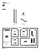
TOOLS NEEDED PARTS [210-1661] (4) Mounting Brackets [205-3214] (1) Electrical Enclosure (2) Edgeline Lights Hardware Bag* [216-1232] (2) Bag A* [216-1227] Bag B* [216-1228] (2) Bag C* [216-1229] [SS672] (12) #10 Screw Cap [SS344] (3) Screw, #8 x 3/8" [SS676] (8) Screw, #10 x 1/2" [203-1068] (3) #8 Lockwasher [SS675] (4) Screw, #10 x 3" [219-1076] (1) Cable Tie Holder [203-1057] (1) 3/32" Allen Key Bag D* [216-1230] [203-1497] (2) Screw, #8 x 3/8" Flat [203-1538] (10) Screw, #8 x 5/8" Flat [2
NOTES Unpack the Lights. Check the box thoroughly for all hardware and loose parts. Carefully inspect the fixture for damage. DANGER: Risk of personal injury. To avoid possible electrical shock, the electricity must be turned off at the circuit breaker or fuse box before attempting any installation procedure. DANGER: Risk of personal injury. To avoid possible electrical shock, the light fixture must be properly grounded.
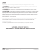
ASSEMBLING THE BRACKETS Note: A RH (Right Hand) installation will require the electrical enclosure to be flipped, placing the exiting low voltage wire closer to the upper bracket. Note: For 1.375 pair installations involving more than one cabinet, a RH installation is required. 1. Orient one of the mounting brackets [210-1661] (as shown) ensuring that the electrical access screws on the electrical enclosure [205-3214] are pointed toward the front of the cabinet. 2.
MOUNTING THE BRACKETS TO THE CABINET Note: When mounting the lights between cabinets, see the following page. 1. Mount the brackets to the cabinet through the ganging locations, as shown, using the supplied #10 screws [SS676]. SS676 SS676 © 2020 Robern, Inc. 701 N. Wilson Ave. Bristol, PA 19007 U.S.A. 800.877.2376 www.robern.com 6 Part no.
MOUNTING THE BRACKETS BETWEEN CABINETS Note: A Ganging Kit (refer to the cabinet's instructions, sold separately) is required for the following instructions. All additional components shown in the following steps will be included with the Ganging Kit. Enough components are included to gang two lights between cabinets. 1. Using two #8 x 3/8" screws [SS344] and two lockwashers [203-1068], attach the mounting brackets to the Electrical Enclosure. 2.
ACCESS THE ELECTRICAL ENCLOSURE Lay the cabinet on a flat level surface. 1. Remove the electrical enclosure cover to access the electrical wiring connections. Set the cover aside in a safe place. 1 ELECTRICAL ENCLOSURE CIRCUIT BREAKER 120VAC 15A FIELD CONNECTION DIMMER* BLACK WHITE * Make proper connections according to the dimmer manufacturer's instructions © 2020 Robern, Inc. 701 N. Wilson Ave. Bristol, PA 19007 U.S.A. 800.877.2376 www.robern.
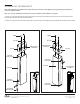
RECESSED INSTALLATION When connecting the Electrical Enclosure to the remote light, it is recommended to route the wiring so that it does not get pinched during recessed mounting. 1. Centered on the cabinet side opposite the electrical enclosure, attach the wire control mount [219-1076] to the cabinet side by peeling and sticking it in place. 2. Route the wire around the back the cabinet until it reaches the wire control mount. 3.
RECESSED INSTALLATION 4. With the electrical cover removed, support the cabinet on the edge of the recessed opening and feed the field wire through the field wire strain relief at the back of each enclosure. 5. Push the cabinet assembly into the recessed opening until the back of the cabinet flange is tight to the finished wall surface. 6. Using a level, level and plumb the products in the opening. Shim as necessary. Using a square, make sure the cabinet is square in all axis. 7.
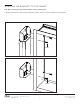
SURFACE INSTALLATION Note: A Surface Mount Kit (refer to the cabinet's instructions, sold separately) is required for the following instructions. All additional components shown in the following steps will be included with the Surface Mount Kit. When connecting the Electrical Enclosure to the remote light, it is recommended to route the wiring so that it does not get pinched during surface mounting. 1.
SURFACE INSTALLATION 4. With the electrical cover removed, feed the field wire through the field wire strain relief at the back of the electrical enclosure. Note: Refer to your cabinet's Instructions to insure there are no additional assembly steps required prior to proceeding. 5. Mount the cabinet in place following the steps provided in the cabinet's instructions. 6. Make the electrical connection according to the electrical diagram on page 8.
SURFACE INSTALLATION 7. Drive the #10 Screws [SS676] provided with the Surface Mount Kit (sold separately) into the holes in the side kit brackets. Use a penny (as detailed in figure 4 below) to set the depth distance. 8. Orienting the sidekit as shown below, insert the Screw Heads into the keyholes on the side of the upper and lower Light Brackets. Note: If the bracket is not oriented correctly, the side kit cannot be lowered into place and may fall resulting in damage. 9.
FINAL ASSEMBLY 1. Close the electrical enclosure using the electrical enclosure cover, set aside in "Access the Electrical Enclosure". Note: Leaving too much Field Wire in the enclosure could prevent it from closing properly and may cause damage to the internal components. 2. Using the provided #8 screws [203-1538] attach an adjustable button receiver [211-1362] to each bracket. The screw head on the button receiver must be facing down. 3.
FINAL ASSEMBLY 4. Connect the electrical connector from the light to the electrical low voltage wire connector coming out of the electrical enclosure. 5. Align and insert the buttons on the back of the light into the upper and lower adjustable button receivers [205-3304]. 6. Slide the light down until it's completely engaged. 3 Surface Mount Recess Mount 4 Button [211-1351] © 2020 Robern, Inc. 701 N. Wilson Ave. Bristol, PA 19007 U.S.A. 800.877.2376 www.robern.com 15 Part no.
PRODUCT ALIGNMENT Note: If the top of the light doesn't align with the top of the cabinet, remove the light and set aside in a safe place before proceeding with the following steps. 1. Remove the lower mounting screw [203-1538] from the adjustable button receiver to access the adjustment screw. 2A. Using the provided Allen key [203-1057] turn the adjustment screw to raise or lower the light into alignment with the cabinet. 2B. Reattach the light and check alignment. Repeated adjustments may be necessary.
PRODUCT ALIGNMENT 3. Adjust the cabinet doors until they align with the lights using the three-way adjustment features in the hinges, adjusted using a #2 Phillips Head screwdriver. 3A. Height: With the hinge slightly closed, you can access the middle screw. This screw will move your door front up and down. 3B. Side to Side/Depth: With the hinge fully extended, you can access the front and back screws. The front screw will adjust the door from side to side and the rear screw will adjust the door's depth. 4.
USE AND MAINTENANCE CAUTION - RISK OF SHOCK Risk of personal injury; disconnect power before servicing. Use only a damp cloth to clean. Ammonia or vinegar-based cleaners can damage the finish. A 50/50 solution of water and isopropyl alcohol is recommended for cleaning the light fixture. When cleaning, spray the cloth, not the light fixture or surround surfaces. Do not use abrasive cleansers on any part of the light fixture.
LAMPE VESPER™ EDGELINE Instructions d'installation Consignes de sécurité importantes - Conserver ces instructions ILUMINACIÓN VESPER™ EDGELINE Instrucciones de instalación Instrucciones de seguridad importantes - Guarde estas instrucciones Convient aux emplacements humides / Adecuadas para ubicaciones húmedas CONTENU CONTENIDO Outils Nécessaires / Pièces - 3 Assemblage des Supports - 5 Montage des Supports sur l'Armoire - 6 Montage des Supports Entre les Armoires - 7 Accéder au Boîtier Électrique - 8
RECOMMANDATIONS AU GRADATEUR RECOMENDACIONES DEL INTERRUPTOR DE ATENUACIÓN Robern recommande d'utiliser le gradateur Maestro® C • L® de LUTRON®, modèle MACL-153M. http://www.lutron.com/TechnicalDocumentLibrary/369613a.pdf Para los modelos regulables, Robern recomienda el Atenuador Maestro® C • L® de LUTRON®, Modelo # MACL-153M. http://www.lutron.com/TechnicalDocumentLibrary/369613a.pdf D'autres gradateurs de commande à LED peuvent fonctionner avec ce produit mais n'ont pas été testés ou vérifiés.
OUTILS NÉCESSAIRES HERRAMIENTAS NECESARIAS PIÈCES PIEZAS [210-1661] (4) Supports de montage / Soportes de montaje [205-3214] (1) Boîtier électrique / Caja eléctrica (2) Edgeline Lumière / Lámpara Sac de Visserie / Bolsa de Herrajes* [216-1232] Sac / Bolsa B* (2) Sac / Bolsa A* [216-1228] [216-1227] [SS675] (4) Vis / Tornillo, #10 x 3" [SS344] (3) Vis / Tornillo, #8 x 3/8" [SS672] (12) Chapeau à vis / Tapapernos [203-1068] (3) #8 Rondelle de blocage / Arandela de seguridad [SS676] (8) Vis / Tornill
REMARQUES NOTAS Déballez la lumière. Vérifiez soigneusement la boîte pour tout le matériel et les pièces détachées. Inspectez soigneusement le luminaire pour tout dommage. Desempaca la luz. Revise la caja a fondo para ver todos los accesorios y piezas sueltas. Inspeccione cuidadosamente el accesorio por daños. DANGER: PELIGRO: Risque de blessures corporelles.
ASSEMBLAGE DES SUPPORTS MONTAJE DE LOS SOPORTES Remarque: Une installation RH (main droite) nécessite que le boîtier électrique soit retourné, plaçant le fil basse tension sortant plus près du support supérieur. Nota: Una instalación RH (mano derecha) requerirá que la caja eléctrica se voltee, colocando el cable de bajo voltaje que sale más cerca del soporte superior. Remarque: Pour les installations à 1,375 paire impliquant plusieurs armoires, une installation RH est requise.
MONTAGE DES SUPPORTS SUR L'ARMOIRE MONTAJE DE LOS SOPORTES AL GABINETE Remarque: Lors du montage des lumières entre les armoires, voir la page suivante. Nota: Cuando monte las luces entre los gabinetes, consulte la siguiente página. 1. Montez les supports sur l'armoire à travers les emplacements de regroupement, comme illustré, à l'aide des vis #10 fournies [SS676]. 1.
MONTAGE DES SUPPORTS ENTRE LES ARMOIRES MONTAJE DE LOS SOPORTES ENTRE GABINETES REMARQUE : Un kit de regroupement (reportez-vous aux instructions de l'armoire, vendu séparément) est requis pour les instructions suivantes. Tous les composants supplémentaires illustrés dans les étapes suivantes seront inclus avec le kit de regroupement. Assez de composants sont inclus pour grouper deux lumières entre les armoires.
ACCÉDER AU COFFRET ÉLECTRIQUE ACCEDA A LA CAJA ELÉCTRICA Coloque el gabinete sobre una superficie plana y nivelada. Posez l'armoire sur une surface plane et de niveau. 1. Retire los dos tornillos de acceso eléctrico #6 [SS217] y las arandelas de seguridad [SS692] para acceder a las conexiones del cableado eléctrico 1. Retirez les deux vis d'accès électrique n° 6 [SS217] et les rondelles de blocage [SS692] pour accéder aux connexions du câblage électrique 2.
INSTALLATION ENCASTRÉE INSTALACIÓN EMPOTRADA Lors de la connexion du boîtier électrique à l'éclairage à distance, il est recommandé de faire passer le câblage de sorte qu'il ne soit pas pincé pendant le montage encastré. Al conectar la caja eléctrica a la luz remota, se recomienda enrutar el cableado para que no se pellizque durante el montaje empotrado. 1.
INSTALACIÓN EMPOTRADA 4. Une fois le (s) capot (s) électrique (s) retiré (s), soutenez le boîtier sur le bord de l'ouverture encastrée et faites passer le (s) fil (s) de terrain à travers la décharge de traction du fil de terrain à l'arrière de chaque boîtier. 4. Con la (s) cubierta (s) eléctrica (s) retirada (s), sostenga el gabinete en el borde de la abertura empotrada y alimente los cables de campo a través del alivio de tensión del cable de campo en la parte posterior de cada caja. 5.
INSTALLATION EN SURFACE INSTALACIÓN EN SUPERFICIE Remarque: Un kit de montage en surface (reportez-vous aux instructions de l'armoire, vendu séparément) est requis pour les instructions suivantes. Tous les composants supplémentaires illustrés dans les étapes suivantes seront inclus avec le kit de montage en surface. Nota: Se requiere un kit de montaje en superficie (consulte las instrucciones del gabinete, que se venden por separado) para las siguientes instrucciones.
INSTALLATION EN SURFACE INSTALACIÓN EN SUPERFICIE 4. Le couvercle électrique étant retiré, faites passer le fil de champ à travers la décharge de traction du fil de champ à l'arrière du boîtier électrique. 4. Con la cubierta eléctrica retirada, alimente el cable de campo a través del alivio de tensión del cable de campo en la parte posterior del gabinete eléctrico.
INSTALLATION EN SURFACE INSTALACIÓN EN SUPERFICIE 7. Insérez les vis n° 10 [SS676] fournies avec le kit de montage en surface (vendu séparément) dans les trous des supports de kit latéraux. Utilisez un sou (comme détaillé dans la figure 4 ci-dessous) pour définir la distance de profondeur. 7. Introduzca los tornillos #10 [SS676] provistos con el kit de montaje en superficie (se vende por separado) en los orificios de los soportes laterales del kit.
L'ASSEMBLAGE FINAL ASAMBLEA FINAL 1. Fermez le boîtier électrique à l'aide du couvercle du boîtier électrique, mis de côté dans «Accès au boîtier électrique». 1. Usando los tornillos de acceso eléctrico [SS217], las arandelas de seguridad [SS692] y la cubierta de la caja eléctrica puesta a un lado en el paso 3, cierre la caja eléctrica. Remarque: Laisser trop de fil de terrain dans le boîtier peut l'empêcher de se fermer correctement et endommager les composants internes.
L'ASSEMBLAGE FINAL ASAMBLEA FINAL 4. Connectez le connecteur électrique de la lumière au connecteur du fil électrique basse tension sortant du boîtier électrique. 4. Conecte el conector eléctrico de la luz al conector del cable eléctrico de bajo voltaje que sale de la caja eléctrica. 5. Alinee e inserte los botones en la parte posterior de la luz en los receptores de botones ajustables superior e inferior [205-3304]. 5.
ALIGNEMENT DES PRODUITS ALINEACIÓN DE PRODUCTOS REMARQUE: Si le haut de la lumière ne s'aligne pas avec le haut de l'armoire, retirez la lumière et mettez-la de côté dans un endroit sûr avant de procéder aux étapes suivantes. NOTA: Si la parte superior de la luz no se alinea con la parte superior del gabinete, retire la luz y guárdela en un lugar seguro antes de continuar con los siguientes pasos. 1.
ALIGNEMENT DES PRODUITS ALINEACIÓN DE PRODUCTOS 3. Ajustez les portes de l'armoire jusqu'à ce qu'elles s'alignent avec les lumières à l'aide des fonctions de réglage à trois voies des charnières, ajustées à l'aide d'un tournevis cruciforme n° 2. 3. Ajuste las puertas del gabinete hasta que se alineen con las luces usando las funciones de ajuste de tres vías en las bisagras, ajustadas con un destornillador Phillips #2. 3A.
UTILISATION ET ENTRETIEN USO Y MANTENIMIENTO ATTENTION - RISQUE DE CHOC PRECAUCIÓN - RIESGO DE SACUDIDA ELÉCTRICA Utilisez uniquement un chiffon humide pour nettoyer. Les nettoyants à base d'ammoniac ou de vinaigre peuvent endommager la finition. Une solution 50/50 d'eau et d'alcool isopropylique est recommandée pour nettoyer le luminaire. Use solo un paño húmedo para limpiar. Los limpiadores a base de amoniaco o vinagre pueden dañar el acabado.