
Installation Guide

ASSEMBLY INSTRUCTIONS FOR YOUR
latitude chandelier
3376
11. Attach hot wire(s) from fi xture (black in color or smooth side of
wire to hot wire from outlet box. Fasten wires together with
wire nut (A) and tightly wrap connection with electrical tape.
12. Attach neutral wire(s) from fi xture (white in color or ribbed side
of wire) to neutral wire from outlet box. Fasten wires together
with wire nut (A) and tightly wrap connection with electrical
tape.
13. Carefully push wire connections back into ceiling outlet box.
14. Slide canopy (I) up extensions (H) and hold fi rmly against
ceiling. Slide collar (J) up extensions (H) and thread onto hang
straight (E) to secure canopy (I) against the ceiling.
15. Remove fl ange (L) from socket (N). Place shade (M) over
socket (N). Thread fl ange (L) back onto the socket to secure the
shade to the fi xture. Repeat this step for the remaining shades.
16. Install fi ve 60W MAX. Type B, candelabra base bulbs into the
sockets.
17. Reconnect main electrical supply at the fuse box/circuit breaker
and test the fi xture.
** To clean, use soft cloth only. Do not use any chemical or
abrasive cleaners as they can damage the fi nish.**
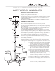
(B)
(C)
(D)
(E)
(F)
(G)
(H)
(K)
(H)
(H)
(H)
(L)
(M)
(I)
(J )
(N)
(A)
IMPORTANT SAFETY INSTRUCTIONS:
*These instructions are provided for your safety. It is important that they are read
completely before beginning installation of fi xture.
*Turn off power at switch before replacing bulbs.
*If any special control devices are used with this fi xture, follow the instructions carefully to
assure full compliance with N.E.C. requirements. If there are any questions, contact a
qualifi ed electrical contractor.
*WE STRONGLY RECOMMEND INSTALLATION BY A LICENSED ELECTRICIAN.
ASSEMBLY INSTRUCTIONS
**SHUT OFF ELECTRICAL SUPPLY AT CIRCUIT BREAKER**
1. Remove all parts carefully from the carton. Do not throw away any parts.
2. Remove cross bar (B) from hang straight (E) by un-threading tube (C) from hang straight
(E). Affi x cross bar (B), including threaded tube (C), to ceiling outlet box using mounting
screws (D) provided.
3. Measure desired drop for fi xture to hang and add/remove extension tubes (H) as needed.
Guide wiring through extensions before threading tubes together.
**TO ADD/REMOVE EXTENSIONS: (Un)Thread the threaded nipple of one extension
into/ out of the threaded opening of the next extension. Make sure electrical cord is pulled
tight when threading extensions together to prevent damage to the wiring.**
4. Thread the bottom extension (H) onto the threaded tube located at the top of housing (K).
5. Guide wiring from top extension (H) through center hole in hang straight (E).
6. Un-thread collar (J) from hang straight (E). Slide collar (J) and canopy (I) down
extensions (H) until they rest on housing (K).
7. Lift fi xture to ceiling outlet box. Guide wiring through threaded tube (C). Thread hang
straight (E) onto threaded tube (C).
8. Connect loop (G) and hang straight (E) using quick link (F).
9. Pull wiring from ceiling outlet box and make proper electrical connections described in
steps 10-12. A LICENSED ELECTRICIAN IS RECOMMENDED.
10. Attach ground wire from fi xture (green or silver) to ground wire from outlet box. Fasten
wires together with wire nut (A) and tightly wrap connection with electrical tape.