
Installation Guide

399
IMPORTANT SAFETY INSTRUCTIONS:
* These instructions are provided for your safety. It’s important that all safety instructions are read before beginning installation of
xture.
* We STRONGLY recommend installation by a licensed electrician.
* Do not connect the electricity until lamp is fully assembled.
* If any special control devices are used with this xture, follow the instructions carefully to assure full commpliance with N.E.C.
requirements. If there are any questions, contact a qualied electrical contractor.
* This xture is UL rated for dry locations.
ASSEMBLY INSTRUCTIONS:
1. SHUT OFF MAIN ELECTRICAL SUPPLY FROM THE MAIN FUSE BOX/CIRCUIT BREAKER.
2. Remove all parts from carton and discard packing materials. Place the parts on a protected work surface.
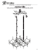
3. Remove mounting plate (A) from canopy (D) by removing screws (E). Set screws (E) aside.
4. Place the mounting plate (A) against the mounting surface so it is aligned with the ceiling outlet box. Once aligned, check to make
sure that the position of the mounting plate is straight. When the proper placement has been conrmed, use a pencil to mark the
locations of the mounting plate support holes (B) onto the mounting surface.
5. Set the mounting plate aside and drill small holes at the marked locations. Holes should be sized so anchors (M), provided, t
securely inside.
6. Push anchors (M) into holes.
7. Carefully pull the wiring from the ceiling outlet box. Thread the wires through the center hole in mounting plate (A).
8. Ax mounting plate (A) to outlet box with mounting screws (C) provided.
9. For additional support, thread mounting screws (L) through holes (B) and into wall anchors (M).
10. Measure desired drop for xture to hang and add/remove extension tubes (I). **TO ADD/REMOVE EXTENSIONS: (Un)Thread
the threaded tube of one extension out of/into the threaded opening of the next extension. Make sure wiring is pulled tight when
threading extensions together to prevent damage to the wire.**
11. Thread bottom extension (I) on to threaded tube (J). Repeat step for other set of extensions.
12. Secure quick link (G) to hang straight (F). Repeat this step for remaining extension set.
13. Guide the wire exiting the xture through loop (H), quick link (G), through the center of hang straight (F), and up
through the hole in canopy (D).
14. Cut the cord to the desired length to make electrical connections. Note: at least 14 inches of wire is needed to make proper
electrical connections.
15. Lift canopy (D) to mounting plate (A) and make proper electrical connections described in steps 16-18. A LICENSED
ELECTRICIN IS RECOMMENDED.
16. Attach ground wire from the xture (green or copper in color) to the ground wire in outlet box. Fasten wires together with wire nut
(N) and tightly wrap connection with electical tape.
17. Attach hot wire from xture (black in color, or smooth side of wire) to hot wire from ceiling outlet box. Fasten wires together with
wire nut (N) and tightly wrap connection with electrical tape.
18. Attach neutral wire from xture (white in color or ribbed side of wire) to neutral wire from ceiling outlet box. Fasten wires
together with wire nut (N) and tightly wrap connection with electrical tape.
19. Gently push wire conections back into ceiling outlet box. Slide canopy (D) over mounting plate (A). Thread screws (E) into holes
in canopy (D) to secure xture to ceiling.
20. Install thirty 40W MAX. Type G candelabra base bulbs into the sockets (K).
21. Reconnect main electrical supply at the fuse box/circuit breaker and test xture.
*** To clean, use a soft dry cloth. Do not use any chemical or abrasive cleaners.***
ASSEMBLY INSTRUCTIONS FOR YOUR
MILANO KINETIC CHANDELIER