
Installation Guide

ASSEMBLY INSTRUCTIONS:
1. SHUT OFF THE MAIN ELECTRICAL SUPPLY FROM THE MAIN FUSE BOX/ CIRCUIT BREAKER.
2. Remove all parts from carton and discard packing materials. Place the parts on a level surface.
3. Remove mounting plate (A) from backplate (C) by unthreading screws (E). Set screws (E) aside.
4. Place the mounting plate (A) against the mounting surface so it is aligned with the wall outlet box. Once aligned, check to make sure that
the mounting plate is level. When proper placement has been conrmed, use a pencil to mark the locations of the mounting plate support
holes (B) onto the mounting surface.
5. Set the mounting plate aside and drill small holes at the marked locations. Holes should be sized so anchors (J) t securely inside.
6. Push anchors (J) into the holes.
7. Carefully pull wires from the wall outlet box and thread them through the center hole in mounting plate (A).
8. Ax mounting plate (A) to wall outlet box with mounting screws (D) provided.
9. For additional support, thread mounting screws (I) through support holes (B) and into wall anchors (J).
10. Lift the backplate (C) to the mounting plate and make the proper electrical connections noted in steps 11 through 13. A LICENSED
ELECTRICIAN IS RECOMMENDED.
11. Attach ground wire from xture (green or copper in color) to ground wire from outlet box. Fasten wires together with wire nut (K)
and tightly wrap connection with electrical tape.
12. Attach hot wire from xture (black in color or smooth side of wire) to hot wire from outlet box. Fasten wires together with wire
nut (K) and tightly wrap connection with electrical tape.
13. Attach neutral wire from xture (white in color or ribbed side of wire) to neutral wire from outlet box. Fasten wires together with
wire nut (K) and tightly wrap connection with electrical tape. Gently push wire connections back into the wall outlet box.
14. Place backplate (C) over mounting plate (A). Use screws (E) to secure the backplate to the mounting surface.
15. Install one 100W max., type A, medium base bulb into the socket (G).
16. Lower shade (F) over bulb and socket (G) until it sits securely in shade housing (H).
17. Reconnect main electrical supply at the fuse box/ circuit breaker and test the xture.
** To clean, use soft cloth only. Do not use any chemical or abrasive cleaners. **
533
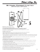
ASSEMBLY INSTRUCTIONS FOR YOUR
(A)
(B)
(C)
(D)
(E)
(F)
(G)
(H)
(I)
(J)
(K)
BOND WALL SCONCE
IMPORTANT SAFETY INSTRUCTIONS:
* These instructions are provided for your safety.
* It is very important that they are read completely before beginning the installation of your xture.
* WE STRONGLY RECOMMEND INSTALLATION BY A LICENSED ELECTRICIAN.
* Turn o power at switch before replacing bulbs, making sure xture has had sucient time to cool down.
* This xture is UL rated for dry locations.