
Installation Guide

CORD COVER ASSEMBLY INSTRUCTIONS:
1. Remove mounting plate (A) from backplate (B) by removing screws (C).
2. Determine desired location for light fi xture on wall. Hold mounting plate (A) in a
level position against the wall. Using a pencil, mark the location of the mounting
holes in mounting plate (A) onto the wall.
3. Drill small holes at marked locations on the wall. Holes should be sized so they
accommodate wall anchors (K), provided. Insert wall anchors into drilled holes.
4. Affi x mounting plate (A) to the wall by threading mounting screws (D) through
holes in mounting plate (A) and into wall anchors.
5. Slide backplate (B) over mounting plate (A). Thread screws (C) back into holes
at the top and sides of backplate (B) to secure fi xture to the mounting surface.
6. Thread cord cover (G) into nipple (E) at the bottom of the backplate. Thread
cord cover (H) onto cord cover (G).
7. Place shades (M) over sockets (L).
8. Insert two 60W MAX. G16.5, Candelabra base bulbs into the sockets (L).
9. Insert three prong plug (I) into the wall outlet.
10. Control power to the fi xture by rotating switch (N).
10. Connect ground (green or silver in color) wire from fi xture to ground wire in the outlet box. Fasten wires together with wire nut (J) and tightly
wrap the connection with electrical tape.
11. Attach hot wire from fi xture (black in color or smooth side of wire) to hot wire from outlet box. Fasten wires together with wire nut (J) and
tightly wrap connection with electrical tape.
12. Attach neutral wire from fi xture (white in color or ribbed side of wire) to neutral wire from outlet box. Fasten wires together with wire nut (J)
and tightly wrap connection with electrical tape.
13. Carefully push wire connections back into wall outlet box. Slide backplate (B) over mounting plate (A).
14. Thread screws (C) into vacant holes at the top and sides of backplate (B) to secure the fi xture to the mounting surface.
15. Place shades (M) over sockets (L). Insert two 60W MAX. G16.5, Candelabra base bulbs into the sockets (L).
16. Reconnect main electrical supply from the fuse box/circuit breaker and test fi xture.
Note: Even when using a wall switch, the fi xture switch (N) must be turned to the ON position for the lamp to function properly.
* To clean, use a soft dry cloth. Do not use any chemical or abrasive cleaners as they may damage the fi nish. *
DIRECT WIRE ASSEMBLY INSTRUCTIONS:
1. SHUT OFF MAIN ELECTRICAL SUPPLY FROM THE MAIN FUSE
BOX/CIRCUIT BREAKER. IT IS RECOMMENDED THAT A LICENSED
ELECTRICIAN INSTALL THIS FIXTURE.
2. Remove mounting plate (A) from backplate (B) by removing screws (C).
3. Cut three prong plug (I) from the end of the electrical cord.
4. Remove cord covers (G) and (H) from the electrical cord. From the back side of
backplate (B), pull the electrical cord up through nipple (E).
5. Cut the cord to the desired length for making an electrical connection. At least
six inches of wire will be needed to make proper electrical connection.
6. Carefully unscrew nipple (E) from backplate (B). Thread plug (F) into hole
vacated by the electrical cord and nipple (E ).
7. Carefully pull the wiring from wall outlet box. Thread the wires through the
center hole in mounting plate (A).
8. Affi x mounting plate (A) to wall outlet box with mounting screws (D) provided.
9. Lift fi xture to mounting plate and make proper electrical connections described
in steps 10 - 12. A LICENSED ELECTRICIAN IS RECOMMENDED.
771
IMPORTANT SAFETY INSTRUCTIONS:
* These instructions are provided for your safety. It’s important that all safety
instructions are read before beginning installation of fi xture.
* We STRONGLY recommend installation by a licensed electrician.
* Turn off power at switch before replacing bulbs, making sure fi xture has had
suffi cient time to cool down.
* Do not connect the electricity until lamp is fully assembled.
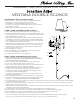
ASSEMBLY INSTRUCTIONS FOR YOUR
VENTANA DOUBLE SCONCE
(A)
(D)
(B)
(C)
(F)
(E)
(G)
(H)
(I)
(J)
(K)
(L)
(M)
(N)