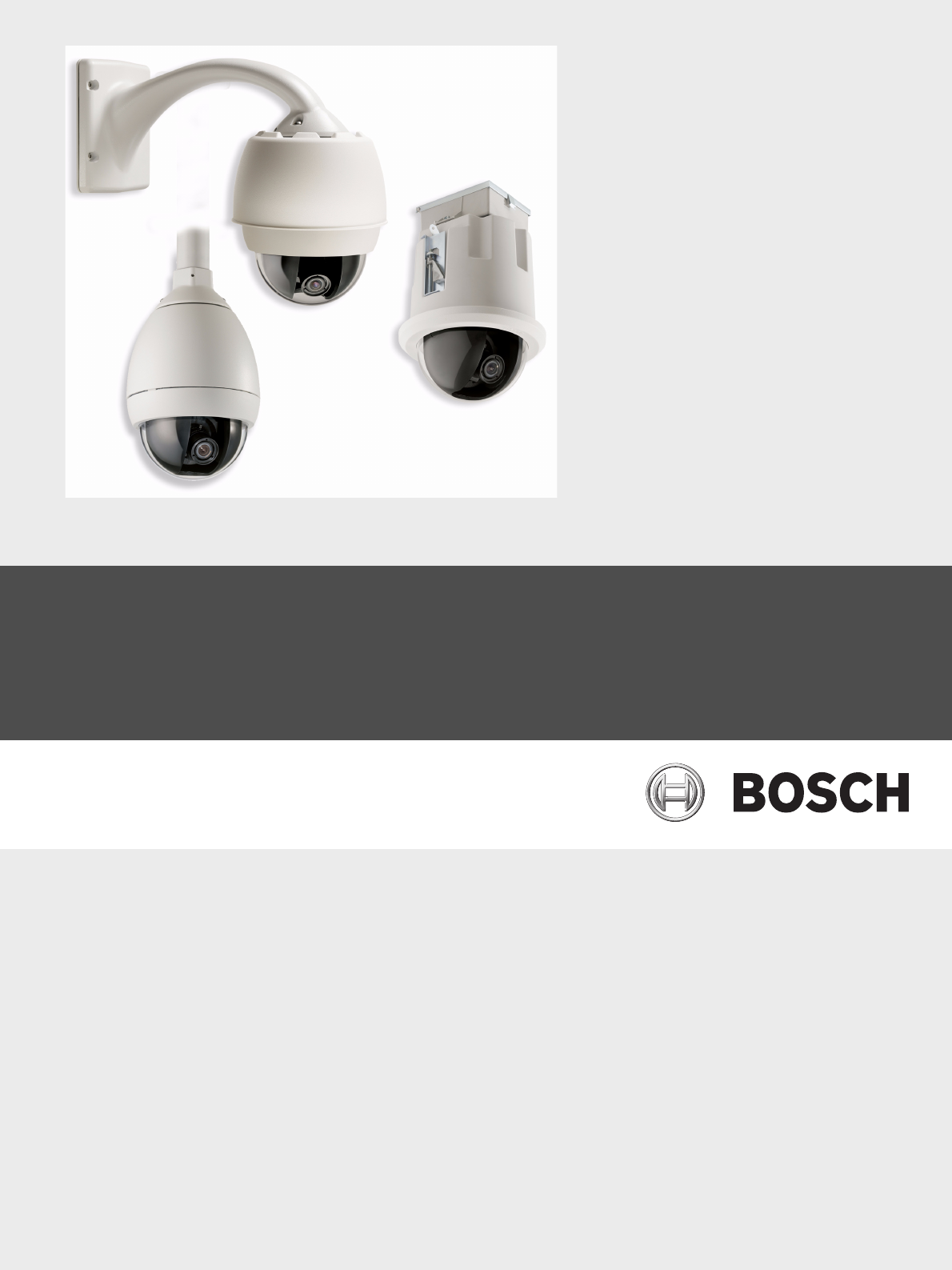
AutoDome Modular Camera System VG4-200 | VG4-300 | VG4-500i en User’s Manual
The following trademarks are registered with the United States Office of Patents and Trademarks: AutoDome, Bosch, and the Bosch logo and symbol are registered trademarks of Robert Bosch, Inc. Microsoft, Microsoft Windows 2000, Microsoft Windows XP, .NET, DirectX, and ActiveX are registered trademarks of Microsoft Corporation. Sun and Java are registered trademarks of Sun Microsystems, Inc. American Dynamics is a registered trademark of Tyco International Ltd. Pelco is registered trademark of Pelco, Inc.
VG4 AutoDome Modular Camera System Table of Contents | en iii Table of Contents 1 Getting Started 3 1.1 Powering On 3 1.2 Establishing AutoDome Control 3 1.2.1 Basic Keyboard Operation 3 1.2.2 Keyboard Commands 4 1.3 Setting the Camera Address 4 1.3.1 FastAddress 4 1.4 Setting Passwords 5 1.4.1 Special Passwords 5 2 On-Screen Display Menu Navigation 7 2.1 Setup Menu 7 2.2 Camera Setup Menu 8 2.3 Lens Setup 11 2.4 PTZ Setup Menu 12 2.5 Display Setup Menu 14 2.
iv en | Table of Contents 6 VG4 AutoDome Modular Camera System Keyboard Commands by Number 37 7 Advanced Features 41 7.1 Alarm Rules (300 and 500i Series Only) 41 7.2 AutoTrack Operation (500i Series Only) 45 7.2.1 AutoTrack Settings and Recommendations 45 7.2.2 AutoTrack Optimization 46 7.3 Virtual Masking (500i Series Only) 47 7.4 Privacy Masking (300 and 500i Series Only) 47 7.
VG4 AutoDome Modular Camera System 9 Table of Contents | en v VG4 Audio Connections 81 9.1 Audio Line Input Specifications 81 9.1.1 Wire Specifications 81 9.1.2 Connections 81 9.1.3 Activating Audio Reception 81 9.1.4 Enabling Audio Transmission 82 9.1.5 Configuring Gain (optional) 83 10 Troubleshooting Guide 85 10.1 VG4 AutoDome Operation and Control 85 10.2 VG4 IP AutoDome Video and Control 88 10.3 VG4 IP AutoDome Audio 89 Bosch Security Systems, Inc. User’s Manual F.
vi en | Table of Contents F.01U.089.433 | 4.0 | 2008.09 VG4 AutoDome Modular Camera System User’s Manual Bosch Security Systems, Inc.
VG4 AutoDome Modular Camera System 1 Getting Started | en 3 Getting Started Install and wire the AutoDome according to the Bosch AutoDome Modular Camera System Installation Manual. A typical system includes a keyboard, matrix switcher, monitor, and appropriate wiring connections. Please refer to the individual product manuals for complete installation and setup instructions for each of the system components. 1.
4 en | Getting Started 1.2.2 VG4 AutoDome Modular Camera System Keyboard Commands Keyboard control commands are composed of a sequence of three (3) inputs with the following convention: 1) a Function key + 2) a Command number key(s) + 3) the Enter key. – Depending on the type of keyboard, the control function keys are labeled: ON or AUX ON OFF or AUX OFF SET or SET SHOT SHOT or SHOW SHOT i NOTICE! The convention used for control key commands in this manual is ON, OFF, SET, and SHOT.
VG4 AutoDome Modular Camera System Getting Started | en 5 To set an address for a camera without an address: 1. Select the camera number you want to FastAddress. The system displays the camera number on the keyboard and the image on the corresponding monitor. 2. 3. Press #-ENTER (where # is the camera number without an address). Press ON-999-ENTER to invoke an on-screen display of cameras on the system without an address. 4. Follow the on-screen instructions.
6 en | Getting Started F.01U.089.433 | 4.0 | 2008.09 VG4 AutoDome Modular Camera System User’s Manual Bosch Security Systems, Inc.
VG4 AutoDome Modular Camera System 2 On-Screen Display Menu Navigation | en 7 On-Screen Display Menu Navigation The AutoDome is programmed through the on-screen display (OSD) menus. To access the OSD menus, you must open the main Setup Menu. Menu items marked with an asterisk (*) are default settings, unless otherwise noted. i 2.1 NOTICE! After a period of 4.5 minutes of inactivity, a menu times-out and exits without warning. Some unsaved settings in the current menu can be lost.
8 en | On-Screen Display Menu Navigation VG4 AutoDome Modular Camera System Menu Description Display Setup Accesses adjustable display settings such as: OSD, sector blanking, and privacy masking. Communication Accesses communication settings such as: AutoBaud and Bilinx. Setup Alarm Setup Accesses the alarm settings such as: inputs, outputs, and rules (not available with 200 Series models). Language Displays the language.
VG4 AutoDome Modular Camera System On-Screen Display Menu Navigation | en 9 Camera Setup Menu Choices: Menu Description Sub-menu / Description Default Setting Exit Exits the menu. White Balance Maintains proper color Extended ATW: Adjusts camera Extended reproduction as the color using extended range. ATW color temperature of a ATW: Adjusts camera color scene changes. For constantly. example, from daylight to fluorescent lighting. Indoor W.B.
10 en | On-Screen Display Menu Navigation Menu VG4 AutoDome Modular Camera System Description Sub-menu / Description Default Setting Shutter Adjusts the electronic Sliding scale: 1/60 sec. shutter speed (AES). – (60 at extreme left to 1/10000) + (NTSC) or 1/50 sec. (PAL) Auto SensUP Sets the limit for Max. sensitivity when the 15x, 7.5x, 4x, or 2x 15x ON, OFF, or AUTO AUTO ON or OFF OFF 55 shutter speed is set to Auto SensUP.
VG4 AutoDome Modular Camera System 2.3 On-Screen Display Menu Navigation | en 11 Lens Setup The Lens Setup Menu provides access to lens settings that can be changed or customized. Menu items marked with an asterisk (*) are the default settings. Lens Setup * * * * * * * Exit...
12 en | On-Screen Display Menu Navigation Menu VG4 AutoDome Modular Camera System Description Sub-menu / Description Default Setting Digital Enables digital zoom. OFF or ON ON Zoom (not available with 200 Series models) Restore Restores all default Defaults settings for this menu. 2.4 PTZ Setup Menu The PTZ Menu provides access to pan/tilt/zoom settings that can be changed or customized. Menu items marked with an asterisk (*) are the default settings. PTZ Setup * * * * * * * * * Exit...
VG4 AutoDome Modular Camera System Menu On-Screen Display Menu Navigation | en Description Sub-menu / Description 13 Default Setting PTZ Fixed Sets pan and tilt speed Speed when controlled by a Sliding scale: – (1 to 15) + 4 Scene 1: Returns to Preset 1. OFF fixed speed controller. Inactivity Selects the mode that an AutoDome reverts to after Prev Aux: Returns to previous the period of inactivity set activity, such as Aux commands 1, in the inactivity period. 2, 7, 8, 50, or 52.
14 2.5 en | On-Screen Display Menu Navigation VG4 AutoDome Modular Camera System Display Setup Menu Provides access to display settings that can be changed or customized. Menu items with an * are the default settings. Display Setup Exit... * Title OSD: * Camera OSD: Display Adjust: Sector Blanking... Privacy Masking...
VG4 AutoDome Modular Camera System Menu On-Screen Display Menu Navigation | en Description Sub-menu / Description 15 Default Setting Privacy Allows masking of Exit: Saves and exits menu. Masking sensitive areas. Up to 24 Mask: 1 to 24 masking areas. Follow the (not privacy masks are on-screen instructions to set a mask. available available, with a See Section 7.4 Privacy Masking (300 and with 200 maximum limit of eight 500i Series Only), Page 47. Series (8) to a scene.
16 en | On-Screen Display Menu Navigation VG4 AutoDome Modular Camera System Communication Setup Menu Choices: Menu Description Sub-menu / Description Default Setting Exit Saves and exits the menu. AutoBaud Turns AutoBaud detection on. ON Toggles ON or OFF. ON automatically accepts baud rates from 2400 to 57600. (Note: If stepping from 2400 to 57600 baud, you must first set the controller to 19200 for AutoBaud to detect the higher baud rate.
VG4 AutoDome Modular Camera System 2.7 On-Screen Display Menu Navigation | en 17 Alarm I/O Setup The Alarm Setup Menu provides access to the Alarm I/O Setup Menu to establish the alarm inputs and outputs and to configure alarm rules. Alarm I/O Setup Inputs Setup Exit... Inputs Setup... Outputs Setup... Rule Setup... Restore Defaults... Exit... 1. Alarm Input 1 2. Alarm Input 2 3. Alarm Input 3 4. Alarm Input 4 5. Alarm Input 5 6. Alarm Input 6 7. Alarm Input 7 8. NONE 9. NONE 10. NONE 11. NONE 12.
18 en | On-Screen Display Menu Navigation Menu VG4 AutoDome Modular Camera System Description Sub-menu / Description Default Setting Inputs 1-7 Defines the type of physical N.O.: Normally open dry contact. input. N.C.: Normally closed dry contact. N.O. N.C.S.: Normally closed supervised contact. N.O.S.: Normally open supervised contact. Inputs 8-12 Defines input commands that NONE: No command defined. can be used in a rule.
VG4 AutoDome Modular Camera System On-Screen Display Menu Navigation | en 19 Outputs Setup Menu Choices Menu Description Sub-menu / Description Default Setting Exit Saves and exits the menu. Outputs Setup Defines physical outputs and keyboard commands for use in a rule. Outputs 1-3 Alarm Relay Defines a physical N.O.: Normally open circuit output. N.C.: Normally closed circuit N.O. A fixed output available for use in a rule.
20 en | On-Screen Display Menu Navigation 2.8 VG4 AutoDome Modular Camera System Rule Setup Menu The Rule Setup Menu shows the status of the rules and lets you add new rules or modify an existing rule. The default setting is Empty. i NOTICE! You can program a total of twelve rules. You must define the inputs and outputs before you program a rule. See Section 2.7 Alarm I/O Setup, Page 17, to configure alarm inputs and outputs. Rule Setup... Exit... 1. Rule 1 2. Rule 2 3. Rule 3 4. Rule 4 5. Rule 5 6.
VG4 AutoDome Modular Camera System On-Screen Display Menu Navigation | en 21 Rule # Choices: Menu Description Sub-menu / Description Default Setting Exit Saves and exits the menu. Enabled Turns the rule on or off after YES to enable or NO to disable NO Toggles through a list of valid Alarm Inputs 1 – 7 and any NONE inputs set in the Alarm I/O additional inputs which were set in Setup > Inputs Setup Menu the Inputs Setup Menu, including that define the rule's inputs.
22 en | On-Screen Display Menu Navigation 2.9 VG4 AutoDome Modular Camera System Language Menu The Language Menu provides access to a list of languages to display the on-screen menus. Language Exit... English Spanish French German Portuguese Polish Italian Dutch Focus / Iris: Save and Exit Language Menu Choices: Menu Description Default Setting Exit Saves and exits the menu. Choose a language Select a language in which the system displays the onscreen menus. 2.
VG4 AutoDome Modular Camera System On-Screen Display Menu Navigation | en 23 Advanced Feature Setup Menu Choices: Menu Description Sub-menu / Description Default Setting Exit Saves and exits the menu. Stabilization Turns on video stabilization. AutoTrack Sets the sensitivity level of Sliding scale: -(Auto, 1 to 20)+ Sensitivity AutoTrack. Where 1 is more sensitive and 20 OFF Auto is less sensitive. Auto varies the sensitivity level based on various lighting conditions.
24 en | On-Screen Display Menu Navigation VG4 AutoDome Modular Camera System Diagnostic Events Menu Description Sub-menu / Description Exit Saves and exits the menu. Alarm Status Enters the Alarm Status menu Alarm Inputs 1 to 7, Alarm and displays the real time status Outputs 1 to 3, and Alarm Relay of alarm inputs and outputs. BIST Enters the Perform Built-in Self YES to start test. NO to exit the Tests menu. If confirmed, the menu.
VG4 AutoDome Modular Camera System On-Screen Display Menu Navigation | en Menu Description Restart Events Displays the number of restart 25 Sub-menu / Description events. Low Volt Events Displays the number of times the AutoDome dropped below the acceptable voltage limit. Power Up Events Displays the number of power up events. Video Loss Events Displays the number of time that video was lost.
26 en | On-Screen Display Menu Navigation F.01U.089.433 | 4.0 | 2008.09 VG4 AutoDome Modular Camera System User’s Manual Bosch Security Systems, Inc.
VG4 AutoDome Modular Camera System 3 Common AutoDome User Commands (unlocked) | en 27 Common AutoDome User Commands (unlocked) This chapter details the commonly used Bosch keyboard setup commands. See Section 6 Keyboard Commands by Number, Page 37, for a complete list of commands. 3.1 Setting AutoPan Mode AutoPan mode pans the AutoDome camera 360º or pans between user defined limits (when programmed). The AutoDome camera continues to pan until stopped by moving the joystick. To pan 360º: 1.
28 en | Common AutoDome User Commands (unlocked) VG4 AutoDome Modular Camera System To add or remove scenes to Preposition Tour 1: 1. Press SHOT-900-ENTER to access the Add/Remove Scenes Menu. 2. Use the Focus/Iris buttons to add or remove the selected scene from the tour. To start custom Preposition Tour 2: (300 and 500i Series Only) Press ON-7-ENTER to start a tour. The tour cycles through the series of shots in the order they were defined until it is stopped.
VG4 AutoDome Modular Camera System 4 Alternative Control Protocols | en 29 Alternative Control Protocols The VG4 AutoDome supports three alternative control protocols that allows a user to send commands and to receive information from the AutoDome. The VG4 AutoDome supports the following protocols: – Pelco-P – Pelco-D – American Dynamics Manchester – Sensormatic RS-422 The VG4 AutoDome natively supports the two Pelco protocols.
30 en | Alternative Control Protocols 4.1.2 VG4 AutoDome Modular Camera System Address Guidelines – An AutoDome with an address set to 0 responds to commands set to any address. – Pelco-P protocol must use addresses 1 to 32. – Pelco-D protocol must use addresses 1 to 254. NOTICE! A previously configured AutoDome with an address above 32 (Pelco-P upper limit) or 254 (Pelco-D upper limit) can be used without readdressing the unit. However, no two (2) i addresses can be the same.
VG4 AutoDome Modular Camera System 4.1.4 Alternative Control Protocols | en 31 Special Preset Commands Some Pelco mode preset commands have a special meaning and override the normal Pelco preset function as follows: Preset Command Description 33-PRESET Pans the AutoDome 180° (Flip). 34-PRESET Goes to Zero Pan (original home position). 80-PRESET Toggles the Synchronization Mode between Line Lock and Internal (Pelco Frame Scan).
32 en | Alternative Control Protocols F.01U.089.433 | 4.0 | 2008.09 VG4 AutoDome Modular Camera System User’s Manual Bosch Security Systems, Inc.
VG4 AutoDome Modular Camera System 5 Pelco On-Screen Menus | en 33 Pelco On-Screen Menus You can program the AutoDome through the Pelco on-screen display (OSD) menus. To access the Pelco menus, you must configure the AutoDome for Pelco Mode and invoke the Pelco main Setup Menu. 5.1 Setup Menu The Pelco main Setup Menu provides access to the programmable AutoDome settings. Some menu items are locked and require a system password to use. Menu items marked with an * are the default settings.
34 en | Pelco On-Screen Menus VG4 AutoDome Modular Camera System Menu Description Exit Exits the menu. Software Version Displays the current software versions. Ack and Reset Alarms Acknowledges and resets active alarms. Restore All Settings Restores all settings to their original default setting. (locked) i 5.1.1 Reset All Memory Clears all settings, including scene shots, tours, and recordings (locked) stored in the AutoDome memory. NOTICE! After a period of 4.
VG4 AutoDome Modular Camera System Pelco On-Screen Menus | en 35 Camera Setup (unlocked) The Pelco Camera Setup Menu provides access to camera settings. Camera Setup Exit... * White Bal: * Night Mode: OUTDOOR AUTO * = Factory Setting Focus / Iris: Select Camera Setup Menu Choices: Menu Description Sub-menu / Description Default Setting Exit Exits the menu.
36 en | Pelco On-Screen Menus VG4 AutoDome Modular Camera System PTZ Setup Menu Choices: Menu Description Sub-menu / Description Default Setting Exit Exits the menu. Edit Tour 1 Accesses the Add / Exit: Exits the menu. (300 and 500i Remove Scenes On Scene (1 - 5): Adds or removes Series) Standard Tour 1 Menu. scenes from the Standard Tour. Edit Tour 2 Accesses the Edit Custom Exit: Exits the menu. (300 and 500i Tour Menu.
VG4 AutoDome Modular Camera System 6 37 Keyboard Commands by Number Function Comm Key No.
38 en | Keyboard Commands by Number Function Comm Key No.
VG4 AutoDome Modular Camera System Locked Function Comm Key No.
40 en | Keyboard Commands by Number F.01U.089.433 | 4.0 | 2008.09 VG4 AutoDome Modular Camera System User’s Manual Bosch Security Systems, Inc.
VG4 AutoDome Modular Camera System 7 Advanced Features | en 41 Advanced Features This chapter details the advanced features of the AutoDome Modular Camera System. 7.1 Alarm Rules (300 and 500i Series Only) The 300 and 500i Series AutoDomes feature a powerful alarm rule engine. In its simplest form, an alarm rule defines those inputs that activate specific outputs. In its more complex form, a rule can be programmed to take any combination of inputs and keyboard commands to perform a dome function.
42 en | Advanced Features VG4 AutoDome Modular Camera System 1. Flash an OSD message (***ALARM 2***) on the monitor. 2. Stop the AutoPan and move the camera to a saved position (Shot 5) viewing the fence. 3. Turn on AutoTrack. 4. Transmit a Bilinx signal to the head end system to trigger an alarm response. The sequence to program this alarm rule example is as follows: 1. i Wire and set the alarm Input(s). a. Wire the motion detector to Input 1. (This circuit is normally open.) b.
VG4 AutoDome Modular Camera System 1. Advanced Features | en 43 Launch the CTFID software from a computer that is connected to a VG4 AutoDome. Figure 7.1 CTFID Overview Window 2. Click the Online Config button and then expand Alarm. Figure 7.2 Expanded Alarm Group 3. Expand Output Options; then click Output Option 5. 4. Select Tracking from the Type drop-down list. 5. Click Output Option 6. 6. Select Shot from the Type drop-down list. Bosch Security Systems, Inc. User’s Manual F.01U.089.
44 en | Advanced Features 7. VG4 AutoDome Modular Camera System Type the number 1 or use the slide bar to specify shot number 1. (Shot numbers must be set prior to configuring an alarm rule. See Section 3.2 Setting Preset Shots, Page 27, for instructions). The AutoDome moves to this preposition when the alarm rule is true. Figure 7.3 Output Option 6 Configuration 8. Expand Alarm Rule; then click Alarm Rule 1. 9. Click the Yes radio button to enable the rule. 10.
VG4 AutoDome Modular Camera System Advanced Features | en 45 16. Select 5 sec from the Output Period drop-down list. This option instructs the AutoDome to turn off the AutoTrack feature after five seconds from when the tracked object is out of view. 7.2 AutoTrack Operation (500i Series Only) The 500i Series AutoDome features enhanced AutoTrack software with more versatility and smoother object tracking.
46 en | Advanced Features VG4 AutoDome Modular Camera System – Mount/Mounting Surface Stability – Mount the camera in the most stable position. Avoid locations affected by vibrations, such as those caused by a roof-top air conditioner. These vibrations may cause complications when the camera zooms-in on a target. – Use the pendant arm mount, if possible. This mount option provides the most – Use guy wires to protect against strong winds if using the parapet mount. stability for the camera.
VG4 AutoDome Modular Camera System Advanced Features | en 47 Setting AutoTrack Optimization Parameters 1. 2. Turn off the command lock (if active): – From a keyboard: press OFF-90-ENTER. – From the Aux Control tab (located on the LivePage view): enter 90-OFF. Access the Main Menu: – From a keyboard: press ON-46-ENTER. – From the Aux Control tab: enter 46-ON. 3. Access the Advanced Feature Setup menu. 4.
48 en | Advanced Features 7.5 VG4 AutoDome Modular Camera System Motion Detection with Region of Interest (500i Series Only) (Preset positions 90 through 99) With the 500i Series AutoDome, the motion detection software can be configured to create a Region of Interest within multiple preset positions or scenes. It can take advantage of Virtual Masking to ignore motion in predefined areas. Motion Detection can also be used as an Alarm Rule input.
VG4 AutoDome Modular Camera System 8 Configuring and Using the IP AutoDome | en 49 Configuring and Using the IP AutoDome The VG4-200, VG4-300, and VG4-500i Series AutoDomes can be ordered with an optional IP module that allows the AutoDome to transmit PTZ control commands and images over a TCP/ IP network. It also allows users to configure the AutoDome camera display settings, camera operating settings, and to configure the network parameters.
50 en | Configuring and Using the IP AutoDome 8.2 VG4 AutoDome Modular Camera System System Requirements The IP AutoDome requires specific software and hardware to allow a user to view live images and to configure camera settings over a TCP/IP network. These requirements are: – A computer with the Microsoft Windows 2000 or XP operating system, network access, and the Microsoft Internet Explorer Web browser version 6.
VG4 AutoDome Modular Camera System Configuring and Using the IP AutoDome | en 51 2 2 3 1 4 2 4 1 Figure 8.1 IP AutoDome System Configuration 1 2 3 4 8.4 AutoDome IP Connection Network Switch Computer Configuring the IP AutoDome Camera To operate the camera in your network you must assign it a valid network IP address. The default IP address is 192.168.0.1, but you may have to change this address if it conflicts with another device on your network.
52 8.5 en | Configuring and Using the IP AutoDome VG4 AutoDome Modular Camera System Installing the Required Software To view live video, you must install Bosch MPEG ActiveX, DirectX, and Java Virtual Machine. To view live video from an IP-enabled VG4 AutoDome in Microsoft Internet Explorer or to change VG4 AutoDome configurations, you must install the following software in this order: 1. Sun Java 2. Microsoft .NET 3. Microsoft DirectX 4. MPEG-ActiveX 5.
VG4 AutoDome Modular Camera System 3. Configuring and Using the IP AutoDome | en 53 Click the Software link under the Download Library section in the left pane. Figure 8.3 Software Link 4. Click OK to agree to the Bosch Software License Agreement. Figure 8.4 Bosch End-user License Agreement 5. Click the CCTV link under the Software heading in the center frame. Figure 8.5 Main Software Frame 6. Click the Cameras, PTZ link to access the software for Bosch PTZ cameras. Figure 8.
54 en | Configuring and Using the IP AutoDome VG4 AutoDome Modular Camera System After you click Cameras, PTZ the browser opens the Software Download page for VG4 and VEZ AutoDomes. Figure 8.7 Required software highlighted 7. Scroll down the page to the AutoDome TCP/IP Communications Module heading. 8. Right-click the appropriate language selection and choose Save Target As from the popup menu for these software packages: 9. – Sun Java – Microsoft .
VG4 AutoDome Modular Camera System Configuring and Using the IP AutoDome | en 55 10. Install the software packages using the procedure below: – Unzip the MPEG-ActiveXXX_enUS_E3366678923.zip and the DirectXXXX_enUS_E2352554507.zip files. Ensure that you maintain the directory structures for each software package. – Double-click the jre-XXXX-windows-i586-p-s_xxXX_XXXXXXXXX.exe file to initiate the Java installation. – Follow the Java Installation Wizard instructions until the software is installed.
56 en | Configuring and Using the IP AutoDome VG4 AutoDome Modular Camera System Using the IP AutoDome Web Server The IP AutoDome incorporates a network video server in the IP module. To configure the camera using the IP AutoDome Web server, do the following: 1. Set the IP address on the PC to 192.168.0.10 to ensure that the PC and the IP AutoDome are on the same Subnet. 2. Launch Microsoft Internet Explorer and navigate to the following URL: http://192.168.0.
VG4 AutoDome Modular Camera System Configuring and Using the IP AutoDome | en 57 11. Disconnect the IP AutoDome Ethernet cable from the dedicated network switch and reconnect the Ethernet cable to the local area network (LAN). 8.6 Main Screen By default, the IP AutoDome opens the LivePage window when started. The main screen is divided into eleven segments as illustrated below. Figure 8.
58 en | Configuring and Using the IP AutoDome 8.7 VG4 AutoDome Modular Camera System Viewing Live Images and Controlling the AutoDome PTZ Once the network cables are properly connected and the IP AutoDome has a valid IP address, you can view live images and control the PTZ controls over the TCP/IP network using Microsoft Internet Explorer. 8.7.
VG4 AutoDome Modular Camera System Configuring and Using the IP AutoDome | en 59 Click either the MPEG-4 Stream 1, the MPEG-4 Stream 2 or the M-JPEG tab to switch between the different displays for the camera image (see Figure 8.11). Figure 8.11 8.7.3 Configuring Data Streams Controlling Camera Operations The View Control tab and the Aux Control tab allow you to control camera functions (pan, tilt, zoom, focus, and iris), navigate through on-screen menus and to view preset shots.
60 en | Configuring and Using the IP AutoDome VG4 AutoDome Modular Camera System To manually pan throughout the image area, move your cursor over any part of the live video. The image area displays a directional arrow (), then click and hold the right mouse key to pan the camera.
VG4 AutoDome Modular Camera System Configuring and Using the IP AutoDome | en 61 Aux Control Tab The Aux Control tab is used to enter pre-programmed keyboard control commands. See Section 6 Keyboard Commands by Number, Page 37, for a list of all commands. To access the Aux Control tab, navigate to the Livepage and click the Aux Control tab (see Figure 8.15 below). i NOTICE! The Aux Control tab can also be used to display the OSD menus.
62 en | Configuring and Using the IP AutoDome VG4 AutoDome Modular Camera System To View a Preset Shot: i 8.8 1. Click the number of the scene you want to view using the on-screen keypad. 2. Click the Show Shot button. NOTICE! For more information about the IP AutoDome settings and controls, click the Help on this page? link to open the IP AutoDome online help.
VG4 AutoDome Modular Camera System Configuring and Using the IP AutoDome | en 63 11. Click the SSL encryption pull-down list and make a selection. The data for the connection, for example the password, can be securely transmitted with SSL encryption. If you have selected the On option, only encrypted ports are offered in the Remote port parameter. 12.
64 en | Configuring and Using the IP AutoDome 8.9 VG4 AutoDome Modular Camera System Partitioning Partitioning can be set for recording images from the cameras connected to the AutoDome; this technique is similar to the partitioning often found on computer hard drives. Before setting a partition, you must chose a Storage Medium by going to the Setting page and clicking on the Recording Settings button. Parameters such as size and type of video recording can be specified for each partition.
VG4 AutoDome Modular Camera System 3. Configuring and Using the IP AutoDome | en 65 Click the Create partition button. The IP AutoDome displays the Create new partition screen. Click the pull-down list for Number of new partitions and select a number, then click Next. i NOTICE! The Recording Scheduler must be stopped before creating a partition. Figure 8.19 4. Figure 8.20 Bosch Security Systems, Inc.
66 en | Configuring and Using the IP AutoDome 5. Click the pull-down list for Recording format and make a selection, then click Next. Figure 8.21 6. VG4 AutoDome Modular Camera System Identifying a Recording Format Click the pull-down list for the Number of alarm tracks, then click Calculate. The IP AutoDome displays the Calculation of alarm track size screen. Figure 8.22 7.
VG4 AutoDome Modular Camera System 8. Configuring and Using the IP AutoDome | en 67 Click the pull-down list for the Type of recording and select the required recording style. Then, click Next. Types of recording: – Ring mode: the recording proceeds continuously. If the maximum hard drive space has been reached, the oldest recordings are overwritten automatically. – Linear mode: the recording proceeds until the entire hard drive space is full.
68 en | Configuring and Using the IP AutoDome – VG4 AutoDome Modular Camera System or Click the Calculate button. The IP AutoDome displays Calculation of partition size screen. Figure 8.26 – Calculating Partition Size Click the drop-down list to select the Standard profile, then click the drop-down list to select the Requested recording time. Click Finish to complete the configuration. All settings are now transferred to the unit and subsequently become effective.
VG4 AutoDome Modular Camera System 4. Configuring and Using the IP AutoDome | en Click the Partition status button. The IP AutoDome displays the Partition status screen. Figure 8.28 Partition Status 5. To view other partitions, click the << and >> buttons. 6. Click OK to close the window. Bosch Security Systems, Inc. 69 User’s Manual F.01U.089.433 | 4.0 | 2008.
70 en | Configuring and Using the IP AutoDome 8.9.2 VG4 AutoDome Modular Camera System Editing a Partition The Edit partition window provides an overview of the current partition configuration, which can be modified at any time. All modifications result in the reorganization of the partition and all sequences stored are lost. It is recommended to back up all important sequences before modifying the partition.
VG4 AutoDome Modular Camera System 8.9.3 Configuring and Using the IP AutoDome | en 71 Deleting Recordings You can delete all recordings in a partition at any time. ! CAUTION! Check the recordings before deleting and back up important sequences on the computer's hard drive. 8.9.4 Click the Format! button to delete all recordings in the selected partition. Deleting all Partitions You can delete all partitions at any time. Individual partitions cannot be deleted.
72 en | Configuring and Using the IP AutoDome VG4 AutoDome Modular Camera System To edit the Recording Scheduler, do the following: 1. 2. Open the IP AutoDome Livepage, then click the Settings tab. Click the Recording Settings link, then click Recording Scheduler. The IP AutoDome displays the Recording Scheduler screen (see Figure 8.30). 3. Click the profile you want to link in the Time periods field. 4.
VG4 AutoDome Modular Camera System 8.10.4 Configuring and Using the IP AutoDome | en 73 Activating the Recording After completing configuration, you must activate the recording scheduler and start the recording. Once recording is underway, the Recording profile and Recording scheduler pages are deactivated and the configuration cannot be modified. To stop the recording activity at any time to modify the settings, do the following: 1. Click the Start button to activate the recording scheduler. 2.
74 en | Configuring and Using the IP AutoDome VG4 AutoDome Modular Camera System To edit the Recording Profile, do the following: 1. 2. Open the IP AutoDome Livepage, then click the Settings tab. Click the Recording Settings link, then click Recording Profiles. The IP AutoDome displays the Recording Profiles screen (see Figure 8.32 above). 3. Click the name of the camera input to edit the settings. To select multiple camera inputs, hold down the shift or [Ctrl] key. 4.
VG4 AutoDome Modular Camera System 8.12.1 Configuring and Using the IP AutoDome | en 75 Creating Alarm Rules Up to four (4) input and output events can be included in a single rule. However, each input and output must be true for the alarm's rule to be valid and enabled. To configure an alarm rule, do the following: 1. 2. Open the IP AutoDome Livepage, then click the Settings tab. Click Alarm from the left pane, then click Alarm Rules. Select an Alarm Rule.
76 en | Configuring and Using the IP AutoDome 8.12.2 VG4 AutoDome Modular Camera System Alarm Rule Examples The following examples provide step-by-step instructions to configure alarm rules from the IPbased Web interface. Basic Alarm Rule Example The following is an example for setting up a basic door alarm rule to: 1. Flash an OSD message (***ALARM 1***) on the display when the alarm is triggered. 2. Move the AutoDome camera to a saved position (for this example use Shot 7). 3.
VG4 AutoDome Modular Camera System 3. Configuring and Using the IP AutoDome | en 77 Close the Input Options list, then expand the Output Options list. Select Output Option 5. – Ensure Output 5 is set to OSD (default setting for Output 5). Figure 8.35 4. Select Output Option 6 (see Figure 8.36 below). a. Click the Type drop-down list and select Shot. b. Move the slider bar or type the number 7 in the Shot field. Figure 8.36 Bosch Security Systems, Inc.
78 en | Configuring and Using the IP AutoDome VG4 AutoDome Modular Camera System 5. Select Output Option 7. 6. Click the Type drop-down list and select Transmit. Figure 8.37 7. a. Move the slider bar or type the number 1 in the Input # field. b. Click the Input Option drop-down list and select 1: Alarm Input 1. c. Move the slider bar or type the number 1 in the Output # field. d. Click the Output Option drop-down list and select 5: OSD. Figure 8.38 F.01U.089.433 | 4.0 | 2008.
VG4 AutoDome Modular Camera System 8. Move the slider bar or type the number 1 in the Output # field. b. Click the Output Option drop-down list and select 5: OSD. Alarm Rule 1 Example Within the Output Options, do the following: a. Move the slider bar or type the number 3 in the Output # field. b. Click the Output Option drop-down list and select 7: Transmit. c. Click the Output Period drop-down list and select 3 sec. d. Click the Yes radio button to enable Alarm Rule 1. Figure 8.
80 en | Configuring and Using the IP AutoDome VG4 AutoDome Modular Camera System Advanced Alarm Rule Example using AutoTrack This example explains how to set an alarm rule that moves the camera to a preset position and then activates the AutoTrack feature to track an intruder after an alarm is triggered. 1. Open the IP AutoDome Livepage, then click the Settings tab. 2. Click the Camera Settings link, click Alarm, then click Output Options. 3. Click Output Option 5 under the Output Options group. 4.
VG4 AutoDome Modular Camera System 9 VG4 Audio Connections | en 81 VG4 Audio Connections The audio version of the VG4 AutoDome has one audio input for line signals. The audio signals are transmitted one-way and in-sync with the video signals. As a result, a door intercom system can be connected at the camera location. i 9.1 NOTICE! The line ports of the intercom should be used for transmitting audio signals on the intercom systems.
82 en | VG4 Audio Connections VG4 AutoDome Modular Camera System Figure 9.1 Configuring Audio Settings 9.1.4 Enabling Audio Transmission To transmit audio via the IP connection, do the following: 1. Open the IP AutoDome LivePage, then click the Settings tab. 2. Click Service Settings from the left pane, then click Livepage Configuration. The IP AutoDome displays the Livepage Configuration screen (see Figure 9.2). 3. Click the Transmit Audio radio button to enable for audio. Figure 9.
VG4 AutoDome Modular Camera System 9.1.5 VG4 Audio Connections | en 83 Configuring Gain (optional) Input gain control is supported over a range of -34B to +12dB. The current video image is shown in the small window next to the slide controls to help verify the audio source and improve the Peak levels. Set the gain of the audio signals to suit your specific requirements. Changes are effective immediately. The current level is displayed next to the slide control to help do this.
84 en | VG4 Audio Connections F.01U.089.433 | 4.0 | 2008.09 VG4 AutoDome Modular Camera System User’s Manual Bosch Security Systems, Inc.
VG4 AutoDome Modular Camera System Troubleshooting Guide | en 10 Troubleshooting Guide 10.1 VG4 AutoDome Operation and Control Problem Solution No video – 85 Check that the Green LED on the AutoDome CPU board is on. This LED indicates video from the camera. If the Green LED is off, then: – Check that the Red LED on the AutoDome CPU board is slowly blinking. This LED indicates power to the AutoDome power supply board and to the CPU Module.
86 en | Troubleshooting Guide No camera control – VG4 AutoDome Modular Camera System Ensure that the keyboard and monitor are set to the correct (same) camera number. If O.K., then: – Check that the camera address is properly set. Enter ON-997-ENTER to display the camera address. If address is not set or is incorrect, then: – Set the camera address using FastAddress (ON-998-ENTER). If O.K.
VG4 AutoDome Modular Camera System Picture is dark – Troubleshooting Guide | en 87 Check that the Gain Control is set to AUTO (ON-43-ENTER). If O.K., then: – Check that the Auto Iris Level is set to the appropriate level (ON-11-ENTER). If O.K., then: – Check that the video coax is terminated with 75 only at the head end. (Double termination causes dark video.) If O.K., then: – Go to the Camera Setup Menu and increase the Pre-Compensation setting.
88 en | Troubleshooting Guide VG4 AutoDome Modular Camera System Low Voltage flashing – If using a non-Bosch power supply, confirm that it meets the Bosch AutoDome power on monitor display ratings. See the AutoDome Datasheet for specifications. If O.K., then: – Check the mains input line voltage. If O.K., then: – Check that the maximum wire length from the power supply has not been exceeded. See the AutoDome Modular Camera System Installation Manual. 10.
VG4 AutoDome Modular Camera System 10.3 Troubleshooting Guide | en 89 VG4 IP AutoDome Audio The following diagrams illustrate the path for audio transmissions between a microphone/ AutoDome and a computer that plays the audio. The first diagram illustrates these connections with an IP-enabled VG4 AutoDome and the second illustration uses an analog (standard) VG4 AutoDome. Use the appropriate diagram to help troubleshoot any audio issues.
90 en | Troubleshooting Guide VG4 AutoDome Modular Camera System Audio Connections with an Analog (standard) VG4 AutoDome In this illustration the analog VG4 AutoDome connects to a Bosch Video/Audio IP Encoder via a coaxial cable. The computer that plays the audio is connected to the encoder via an Ethernet cable. Figure 10.
VG4 AutoDome Modular Camera System Problem Solution No Audio – Troubleshooting Guide | en 91 Check the computer receiving the audio from the VG4 AutoDome or from the IP Encoder. – Check the computer’s audio settings. Ensure that the sound levels are at an audible – Check the computer’s audio output card and speakers. Play a secondary source of level. audio on the computer. If you still do not hear audio replace the speakers and try again. If O.K.
92 en | Troubleshooting Guide Problem VG4 AutoDome Modular Camera System Solution If O.K., then: – Check all network connections. – If the video is clear and contains no distortion, then the network connections are probably not the source of audio problems. – Ensure that the maximum distance between any two Ethernet connections is 100 m (328 ft). Refer to the AutoDome Modular Camera System Installation Manual for more information.
VG4 AutoDome Modular Camera System A | en 93 User Command Table Function Comm Key No.
94 en | VG4 AutoDome Modular Camera System Function Comm Key No.
VG4 AutoDome Modular Camera System Glossary of CCTV Terms | en 95 Glossary of CCTV Terms A Address Each AutoDome has a numerical address in the control system in which it is located. This allows the appropriate dome to be operated. The address may be set locally using the Bilinx Configuration Tool for Imaging Devices (CTFID) or remotely using the Fast Address function (see Fast Address). AAC See Advanced Alarm Control.
96 en | Glossary of CCTV Terms Auto White Balance VG4 AutoDome Modular Camera System A feature that allows a color camera to automatically adjust its output color to give a natural color independent of the lighting used. AWB See Auto White Balance. B Back Light Compensation Selectively amplifies parts of the image to compensate for large contrast differences when only a portion of the image is brightly lit (e.g. a person in a sunlit doorway). Balun Short for Balance/Unbalanced.
VG4 AutoDome Modular Camera System Glossary of CCTV Terms | en 97 D Day/Night (IR sensitive) An AutoDome that has normal color operation in situations where there is sufficient illumination (day conditions), but where the sensitivity can be increased when there is little light available (night conditions). This is achieved by removing the infrared cut filter required for good color rendition.
98 en | Glossary of CCTV Terms Focal Length VG4 AutoDome Modular Camera System The distance from the optical center of the lens to the image of an object located at an infinite distance from the lens. Long focal lengths give a small field of view (e.g. telephoto effect), while short focal lengths give a wide angle view. F-Number The standard measure of the lens aperture, which is the iris diameter, divided by the focal length of the lens.
VG4 AutoDome Modular Camera System Glossary of CCTV Terms | en IPS See Images per Second. IRE See Institute of Radio Engineers. 99 L Lux The International (SI) unit of measurement of the intensity of light. It is equal to the illumination of a surface one meter away from a single candle. M MJPEG Motion JPEG is a digital video encoding standard where each video frame is separately compressed into a JPEG image. Modal Dispersion A broadening of a waveform over long distances.
100 en | Glossary of CCTV Terms VG4 AutoDome Modular Camera System N National Pipe Thread A U.S. standard for tapered threads. NPT sizes measure the nominal inside diameter of the pipe. NPT threads form a seal as the threads compress against each other. NEMA Rating Specification standards in reference to the operating environment for a variety of electrical devices.
VG4 AutoDome Modular Camera System Glossary of CCTV Terms | en 101 S Sector Blanking The ability to blank out video in any of the 16 pan sectors. Sensitivity A measure of the amount of light required to provide a standard video signal. Sensitivity values are stated in lux or foot-candles. SensUp Increases camera sensitivity by increasing the integration time on the CCD. This is accomplished by integrating the signal from a number of consecutive video frames to reduce signal noise.
102 en | Glossary of CCTV Terms VG4 AutoDome Modular Camera System V Virtual Masking A unique Bosch technology that allows for the creation of “invisible” motion masking areas. These invisible masks are similar to privacy zones, but only the AutoDome’s AutoTrack II and Video Motion Detection algorithms can see them. This allows the AutoDome to ignore areas of unwanted motion.
VG4 AutoDome Modular Camera System Index | en 103 Index Symbols .
104 en | Index C camera height 23 operations 59 OSD 14 setup 33 camera height 45 Camera Setup menu 7, 8, 35 AutoSensUp maximum 10 backlight compensation 9 gain control 9 line lock delay 9 line lock 9 maximum gain level 9 night mode 10 color 10 threshold 10 pre-compensation 10 sharpness 9 shutter 10 synchronization mode crystal 9 line lock 9 synchronization menu 9 white balance 9 AWB hold 9 extended ATW 9 indoor white balance 9 outdoor white balance 9 command lock 33 Command Lock menu 34 command numbers 60
VG4 AutoDome Modular Camera System internal temperature 24 low temperature events 24 low volt events 25 power up events 25 restart events 25 security access 24 video loss events 25 Dibos 50 digital I/O 60 digital zoom 12 DirectX 50, 52 display adjust 14 Display Setup menu 8, 14 camera OSD 14 display adjust 14 privacy masking 15 sector blanking 14 title OSD 14 displaying camera response information 14 on-screen menus 60 sector titles 14 shot titles 14 software version 36 titles 14 dual streaming 49 dwell pe
106 en | Index L Language menu 8, 22 Lens Setup menu 7, 11 auto focus 11 constant focus 11 manual focus 11 spot focus 11 auto iris 11 constant iris 11 manual iris 11 auto iris level 11 digital zoom 12 focus speed 11 iris speed 11 maximum zoom speed 11 light conditions 46 limit stops 31, 33, 36 line level 92 line lock 9, 31 Livepage 56, 58 low temperature events 24 threshold 24 low volt events 25 M Manchester 29 manual focus 11 iris 11 masking privacy 15 virtual 23 maximum zoom speed 11 menus Advanced Fea
VG4 AutoDome Modular Camera System 93-PRESET 31 94-PRESET 31 95-PRESET 31, 33 96-PRESET 31 97-PRESET 31 98-PRESET 31 99-PRESET 31 AutoScan 31 FastAddress 31 frame scan 31 limit stops 31 PRESET 30 preset tour 31 random scan 31 synchronization mode 31 zero pan 31 menus 33 Bosch 34 Camera Setup 35 night mode 35 white balance 35 Command Lock 34 Other 36 ack 36 acknowledge alarm 36 FastAddress 36 password 36 reset alarm 36 software version 36 PTZ Setup 35 AutoPivot 36 custom tour 36 edit standard tour 36 limit
108 en | Index playback 28 region of interest 48 reset alarm 34, 36 restart events 25 RS-422 29 rule choices alarm relay 21 Aux Off 21 Aux On 21 enabled 21 follows 21 input 21 OSD 21 output 21 Shot 21 transmit 21 input Shot 21 status 20 rule (1-12) 20 Rule Setup menu 20 rules 20 S scan speed 33, 36 scene 1 13 sector blanking 14 security access 24 level 5 Sensormatic 29 SensUp 10 Set command 27 Set Shot 60, 61 SET-100-ENTER 27 SET-802-ENTER 5 settings AutoDome orientation 13 autopan 27 brightness 14 camer
VG4 AutoDome Modular Camera System Index | en 109 U UDP 49, 88 user commands 27 V video loss events 25 video transmission 88 VIDOS 50 View Control tab 59 VIP XD 50 virtual masking 23, 47 voltage limit 25 W white balance 9, 35 Z zero pan 31 zoom 59 Bosch Security Systems, Inc. User’s Manual F.01U.089.433 | 4.0 | 2008.
110 en | Index F.01U.089.433 | 4.0 | 2008.09 VG4 AutoDome Modular Camera System User’s Manual Bosch Security Systems, Inc.
Americas Bosch Security Systems, Inc. 850 Greenfield Road Lancaster, Pennsylvania 17601 USA Telephone +1 888-289-0096 Fax +1 585-223-9180 Email: security.sales@us.bosch.com www.boschsecurity.us Europe, Middle East, Africa: Bosch Security Systems B.V. P.O. Box 80002 5600 JB Eindhoven, The Netherlands Phone: + 31 40 2577 284 Fax: +31 40 2577 330 emea.securitysystems@bosch.com www.boschsecurity.