
- Roberts-Gordon user guide heater CTCU 7, CTCU 11, CTCU 15, CTCU 22, CTCU 27, CTCU


SECTION 15: REMOVAL AND REPLACEMENT PARTS
31
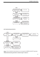
15.6 Ignition Control
The control plugs onto the gas valve. Pull out 12 pin
electrical connection. Pull out ignition cable and
flame probe cable noting their positions
Release screw securing control to gas valve.
Refit in reverse. Ensure correct location of ignition
and flame probe cables. Ensure that the earth
connection is made directly to the earth point on the
gas valve.
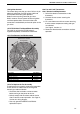
15.7 CTCUA Axial Fan/Guard/Motor Assembly
The axial fan unit for the CTCUA heater is
supplied completely assembled and balanced.
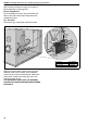
15.7.1 Fan Removal and Replacement
15.7.2 To Replace the Fan Assembly
To replace the fan assembly, reverse the procedure
shown above. Fit rubber washers to the guard
mountings to reduce vibration.
• Check that the fan blades are free to rotate
before turning on the power to the fan.
• Strictly comply with the colour code of the fan
wires to ensure correct operation. See Page 14,
Section 9.3 wiring diagram.
• Use only genuine ROBERTS GORDON
®
replacement parts.
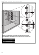
15.8 Fan and Limit Thermostats
15.8.1 Removal and Replacement
1. Pull off the electrical connections to the
thermostat
2. Unscrew the two screws securing the
thermostat
3. Fit a new thermostat with two screws ensuring
that the correct temperature setting and type
are selected.
See Page 6, Section 4.3.
4. Reconnect the electrical connections and test
operation.
Remove the screws
and washers.
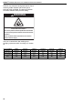
Description Part Number
Axial Fan CTCU-7 11111910
Ax i al Fan CT C U- 11 111119 11
Ax i al Fan CT C U- 15 111119 2 0
Ax i al Fan CT C U- 2 2 111119 2 1
Ax i al Fan CT C U- 2 7 /3 2 1111192 2