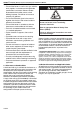
FOR YOUR SAFETY If you smell gas: 1. Open windows. 2. DO NOT try to light any appliance. 3. DO NOT use electrical switches. 4. DO NOT use any telephone in your building. 5. Extinguish any open flame. 6. Leave the building. 7. Immediately call your local gas supplier after leaving the building. Follow the gas supplier’s instructions. 8. If you cannot reach your gas supplier, call the Fire Department.
TABLE OF CONTENTS SECTION 1: Heater Safety...................................................... 2 1.1 Manpower Requirements ............................................. 2 1.2 Safety Labels and Their Placement ............................. 2 SECTION 2: Installer Responsibility ..................................... 4 2.1 Clearances to Combustibles ........................................ 4 2.2 Corrosive Chemicals.................................................... 4 2.
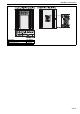
TABLE OF FIGURES Figure 1: Front and Back Panel Label Placement ..................... 2 Figure 2: Side Panel Label Placement...................................... 3 Figure 3: Installation Clearances and Clearances to Combustibles............................................................. 6 Figure 4: Suspension Methods ............................................... 11 Figure 5: Shelf Mounting and Hanging Suspension................ 12 Figure 6: Vertical Louvres (Optional) ..................................
COMBAT® Compact Tubular Unit Heaters are high efficiency heaters and are listed on the Enhanced Capital Allowance Scheme ’Energy Technology Product List’. The ETL symbol is a UK registered certification mark of The Carbon Trust.
COMBAT® CTCU UNIT HEATERS INSTALLATION OPERATION AND SERVICE MANUAL SECTION 1: HEATER SAFETY Your Safety is Important to Us! This symbol is used throughout the manual to notify you of possible fire, electrical or burn hazards. Please pay special attention when reading and following the warnings in these sections. Installation, service and annual inspection of heater must be done by a registered installer/contractor qualified in the installation and service of gas-fired heating equipment.
SECTION 1: HEATER SAFETY Figure 2: Side Panel Label Placement Description Lighting Label Wiring Diagram Label Part Number 91040002 91040020 3 of 42
COMBAT® CTCU UNIT HEATERS INSTALLATION OPERATION AND SERVICE MANUAL SECTION 2: INSTALLER RESPONSIBILITY • To install the heater, as well as the gas and electrical supplies, in accordance with applicable specifications and codes. Roberts-Gordon recommends the installer contact a local building inspector, Fire Officer or insurance company for guidance. • To use the information given in the manual together with the local and national codes to perform the installation.
SECTION 3: CLEARANCES TO COMBUSTIBLES SECTION 3: CLEARANCES TO COMBUSTIBLES WARNING • Fire Hazard Keep all flammable objects, liquids and vapours the minimum required clearances to combustibles away from heater. • Some objects will catch fire or explode when placed close to heater. Failure to follow these instructions can result in death, injury or property damage. 3.
COMBAT® CTCU UNIT HEATERS INSTALLATION OPERATION AND SERVICE MANUAL Figure 3: Installation Clearances and Clearances to Combustibles * Heaters may be mounted at a higher level if destratification **80 cm is necessary to service fans are installed. heater. The heater must always be installed at least 1.8 m above the floor. The flue pipe must have clearance from combustibles by 5 cm.
SECTION 4: CRITCAL CONSIDERATIONS SECTION 4: CRITCAL CONSIDERATIONS 4.1 Ventilation WARNING Carbon Monoxide Hazard Heaters may be installed vented or unvented. Vented heaters must be vented outdoors. Unvented heaters must be installed in buildings with ventilation rates as per section 7. Failure to follow these instructions can result in death or injury.
COMBAT® CTCU UNIT HEATERS INSTALLATION OPERATION AND SERVICE MANUAL SECTION 5: SPECIFICATIONS 5.
SECTION 5: SPECIFICATIONS 5.2 General Technical Data Table (All Models) Model CTCU-7 CTCU-11 CTCU-15 CTCU-22 CTCU-27 / 32 Total Electrical Load W 260 274 336 384 345 Run Current A 1.1 1.2 1.5 1.7 1.5 Start Current A 1.7 1.8 2.5 2.9 2.6 Air Flow m3/h 1120 1220 2710 2750 4474 Air Throw m 9 12 14 16 16 [NR] dB(A) [31] 37 [35] 41 [39] 45 [42] 48 [42] 48 mm Ø 80 80 80 80 100 m 2.
COMBAT® CTCU UNIT HEATERS INSTALLATION OPERATION AND SERVICE MANUAL SECTION 6: HEATER INSTALLATION 6.1 General Heaters are designed for installation above 2.5 m. These heaters must be installed within the heated space. Duct delivery systems are not permitted with axial fans. When handling or supporting the heater from below, ensure that the weight is taken at the support points. 6.2 Basic Information CTCU heaters have automatic ignition burners for ON/OFF operation only. 6.
SECTION 6: HEATER INSTALLATION Figure 4: Suspension Methods Unistrut Channel Nut Ensure all suspension hardware is torqued to a minimum of 27 Nm (20 ft lbs). Washer Nut 10 mm Steel Drop Rod Cone Point Set Pin Window Clamp 10 mm Steel Drop Rod Unistrut Nut Washer Description Part Number Shelf Mounting Bracket 11111510K Kit Shelf Mounting Bracket (2) 111111510 Screw #10 x 1/2" 94311008 Type AB Phil HWH Z (2) Riv Nut Shelf Mounting Brackets Qty.
COMBAT® CTCU UNIT HEATERS INSTALLATION OPERATION AND SERVICE MANUAL Figure 5: Shelf Mounting and Hanging Suspension Shelf Mounting Hanging Shelf Mounting Brackets (Fasten to Wall Mounting Bracket) Wall Mounting Bracket Arm (Right & Left) Wall Mounting Bracket Diagonal Wall Mounting Bracket Vertical Description Wall Shelf Mounting Bracket Kit Wall Suspension Mounting Bracket Kit Shelf Mounting Bracket Kit M10 Fasteners M8 Bolt Washer Lock Washer M8 Locknut Torque to 4.
SECTION 7: FLUE INSTALLATION SECTION 7: FLUE INSTALLATION 7.1 Flue Installation WARNING Carbon Monoxide Hazard Heaters installed unvented must be interlocked with sufficient building exhaust. Heaters must be installed according to the installation manual. Failure to follow these instructions can result in death or injury. WARNING Fire Hazard Keep all flammable objects, liquids and vapours the minimum required clearances to combustibles away from heater.
COMBAT® CTCU UNIT HEATERS INSTALLATION OPERATION AND SERVICE MANUAL Figure 7: Flue and Roof Detail Flue Terminal Masterflash Soaker Flashing or Rain Collar.
SECTION 7: FLUE INSTALLATION Figure 9: Vertical and Horizontal Flue Termination - Type C12 C32 & C62 Appliances Roof Terminal Plastic Cup Masterflash Manifold Air Intake Vertical Option Remove Internal Wire Mesh Flue Horizontal Option Wall Plate Flue Air Intake Remove Internal Wire Mesh Manifold Wall Terminal 15 of 42
COMBAT® CTCU UNIT HEATERS INSTALLATION OPERATION AND SERVICE MANUAL SECTION 8: AIR SUPPLY 8.1 Room Sealed Installation When installed as a room sealed heater, the air for combustion is drawn in from outside the building. It is important to ensure that there is adequate ventilation to provide air for the distribution fan/s. 8.
SECTION 9: GAS PIPE WORK SECTION 9: GAS PIPE WORK • The gas supply pipe is adequately sized to carry the total volume of gas for the complete installation. • An isolating valve and union connection should be used and fitted into the supply adjacent to the heater. • For suspended heaters, use an approved metal flexible connection between the isolating valve and the heater. To reduce pressure loss, use one pipe size larger than the heater gas connection.
COMBAT® CTCU UNIT HEATERS INSTALLATION OPERATION AND SERVICE MANUAL Figure 10: Gas Connection with Stainless Steel Flex Connector 18 of 42
SECTION 10: WIRING AND ELECTRICAL INFORMATION SECTION 10: WIRING AND ELECTRICAL INFORMATION DANGER Electrical Shock Hazard Disconnect electric before service. Heater must be properly grounded. Failure to follow these instructions can result in death or electrical shock. 10.1 Electrical Supply All heaters need a constant 230 V 50 Hz single phase supply connected to terminals L, N & Earth. Polarity "L & N" must be correct. The voltage between neutral and earth should be 0 and never exceed 15 volts.
COMBAT® CTCU UNIT HEATERS INSTALLATION OPERATION AND SERVICE MANUAL 10.3 CTCUA Wiring Diagram (Models 7-32) NOTE: If any of the original wire supplied with the heater must be replaced, it must be replaced with wiring material having a temperature rating of at least 105° C and 600 volts.
SECTION 11: COMMISSIONING SECTION 11: COMMISSIONING WARNING DANGER Electrical Shock Hazard Disconnect electric before service. Explosion Hazard Turn off gas supply to heater before service. More than one disconnect switch may be required to disconnect electric from heater. Burn Hazard Allow heater to cool before service. Cut/Pinch Hazard Wear protective gear during installation, operation and service. Tubing may still be hot Edges are sharp. after operation.
COMBAT® CTCU UNIT HEATERS INSTALLATION OPERATION AND SERVICE MANUAL 2. Using the installed external control, turn on the 11.4 Begin Commissioning burner. The automatic sequence will now begin 11.4.1 Before Operating the Heater as described on Page 22, Figure 11. To ensure that all the controls are in safe working There will be no ignition of the burner and lockout order, operate the heater for the first time with the will occur, which proves the controls are operating isolating gas valve turned off.
SECTION 11: COMMISSIONING Figure 12: Gas Valve for Heater (Models 7 - 32) 11.4.2 Commissioning the Gas Valves (all gases) 11.4.2.1 Check Burner Gas Pressure 1. Loosen the screw cover of the outlet (burner) pressure test point and connect a manometer. 2. With the burner firing, measure the pressure on the manometer.
COMBAT® CTCU UNIT HEATERS INSTALLATION OPERATION AND SERVICE MANUAL 11.8 Complete the Commissioning Ensure that all covers are fitted correctly and all test points are properly sealed. 11.9 Instruction to the User Explain the controls of the heater to the user including how to turn it on and off, using the controls fitted on site. Give this manual to the user.
SECTION 12: USER INSTRUCTIONS SECTION 12: USER INSTRUCTIONS DANGER Electrical Shock Hazard Disconnect electric before service. Heater must be properly grounded. Failure to follow these instructions can result in death or electrical shock. WARNING Fire Hazard Keep all flammable objects, liquids and vapors the minimum required clearances to combustibles away from heater. Explosion Hazard Turn off gas supply to heater before service. Burn Hazard Allow heater to cool before service.
COMBAT® CTCU UNIT HEATERS INSTALLATION OPERATION AND SERVICE MANUAL 12.3.2 Limit Thermostat The limit thermostat is located inside the access door of the heater. See Page 38, Section 16.3. This control protects the heat exchanger against overheating. 3. The time and/or temperature controls are not “ON”. 4. The thermostat limit thermodisc may have operated. This may be caused by an interruption of the electrical supply or failure of the distribution fan.
SECTION 13: SERVICING SECTION 13: SERVICING WARNING DANGER Electrical Shock Hazard Disconnect electric before service. Explosion Hazard Turn off gas supply to heater before service. More than one disconnect switch may be required to disconnect electric from heater. Burn Hazard Allow heater to cool before service. Cut/Pinch Hazard Wear protective gear during installation, operation and service. Tubing may still be hot Edges are sharp. after operation.
COMBAT® CTCU UNIT HEATERS INSTALLATION OPERATION AND SERVICE MANUAL heat exchanger. Look for signs of overheating at the front tubes which may indicate burner over firing or persistently low air flows. 13.5 Gas Control Valve Maintenance No regular maintenance is required on these devices. To change gas control valves, See Page 36, Step 16.1. Do not repair or disassemble on site. Replace faulty gas valves with genuine replacement parts sold and supplied by Roberts-Gordon. 13.
SECTION 13: SERVICING Burner Observation Window Make sure it is clean and free of cracks or holes. Clean and replace as required. Flue Blower Scroll, Wheel Compressed air or a vacuum cleaner may be used to clean dust and dirt. and Motor Inshot Burners and Clear obstructions (even spider webs will cause problems). Orifices Carefully remove any dust and debris from the burner. Direct-Spark Igniter Replace if there are cracked ceramics, excessive carbon residue, or erosion of the electrode.
COMBAT® CTCU UNIT HEATERS INSTALLATION OPERATION AND SERVICE MANUAL SECTION 14: CONVERSION BETWEEN GASES 14.1 General Conversion between gases will require a change of burner injectors and the gas valve re-commissioning to the new conditions. 14.2 Burner Conversion Conversion of the burner assembly from one gas to the other is the same for all types of heaters. 1. Remove the burner compartment cover as shown on Page 37, Section 16.2. 2. Remove the connection between the gas valve outlet and the manifold.
SECTION 15: TROUBLESHOOTING SECTION 15: TROUBLESHOOTING DANGER Electrical Shock Hazard Disconnect electric before service. Heater must be properly grounded. Failure to follow these instructions can result in death or electrical shock. WARNING Fire Hazard Keep all flammable objects, liquids and vapors the minimum required clearances to combustibles away from heater. Explosion Hazard Turn off gas supply to heater before service. Burn Hazard Allow heater to cool before service.
COMBAT® CTCU UNIT HEATERS INSTALLATION OPERATION AND SERVICE MANUAL 15.1 General For your safety and optimum heater performance, use only ROBERTS GORDON® replacement parts. Conduct Commissioning procedure as shown on Page 21, Section 11.
SECTION 15: TROUBLESHOOTING 15.2 Troubleshooting For Automatic Ignition Burner Systems For your safety and optimum heater performance, use only ROBERTS GORDON® replacement parts. Conduct Commissioning procedure as shown on Page 21, Section 11.
COMBAT® CTCU UNIT HEATERS INSTALLATION OPERATION AND SERVICE MANUAL 15.3 Troubleshooting for Flame Supervision System To measure flame current, connect a 0 - 50 µA DC meter in series with the flame probe. If the meter reads negative values, then reverse the test leads. NOTE: Minimum flame probe current 1 µA DC. 15.
SECTION 15: TROUBLESHOOTING 15.5 Troubleshooting for Main Fan For your safety and optimum heater performance, use only genuine ROBERTS GORDON® replacement parts. Conduct Commissioning procedure as shown on Page 21, Section 11.
COMBAT® CTCU UNIT HEATERS INSTALLATION OPERATION AND SERVICE MANUAL SECTION 16: REMOVAL AND REPLACEMENT PARTS WARNING DANGER Electrical Shock Hazard Explosion Hazard Fire Hazard Carbon Monoxide Hazard Use only genuine ROBERTS GORDON® replacement parts per this installation, operation and service manual. Failure to follow these instructions can result in death, electric shock, injury or property damage. See warnings and notes on Page 27, Section 13 before removing or replacing parts.
SECTION 16: REMOVAL AND REPLACEMENT PARTS 16.2 Burner Compartment Burner Compartment Cover Viewing port for flame probe Flame Probe The burner compartment is a sealed compartment. Following any work, re-seal the compartment with the gas pipe rubber seal fully in place and all screws fitted and tight. Ignition Electrode Remove flexible air duct from spigot Remove screws and pull off burner cover 16.2.1 Burner Injectors Manifold Remove manifold screws and pull out manifold.
COMBAT® CTCU UNIT HEATERS INSTALLATION OPERATION AND SERVICE MANUAL 16.3 Ignition Electrode and Flame Probe Burners Limit Thermostat Flame Probe Flame Probe Fan Thermostat Ignition Electrode Ignition Electrode .120 (3 mm) spark gap Burners Burner Compartment Front Views To replace the ignition electrode or flame probe, remove the electrical lead and screw. Pull out from mounting. Refit in reverse ensuring that the gap to burner is as shown in the front view of the burner compartment.
SECTION 16: REMOVAL AND REPLACEMENT PARTS 16.4 Flue Fan Vertical Installation (Models 7 - 15) 1. To remove the fan, remove 3 screws securing the fan/ mounting plate to the vent box. 2. To remove the fan from the mounting plate, remove the 4 screws. 3. Refit in reverse order. 4. To change the flue and air intake orientation from back to top, remove the fan/mounting plate as explained in Steps 1 and 2. 5. Remove intake and exhaust cover(s) from top of the heater. 6.
COMBAT® CTCU UNIT HEATERS INSTALLATION OPERATION AND SERVICE MANUAL 16.5 Flue Fan Vertical Installation (Models 22 - 32) 1. To remove the fan, remove 5 screws securing the fan/ mounting plate to the vent box. 2. To remove the fan from the mounting plate, remove the 2 screws. 3. Refit in reverse order. 4. To change the flue and air intake orientation from back to top, remove the fan/mounting plate as explained in Steps 1 and 2. 5. Rotate the motor 90º counterclockwise and reinstall the 3 screws. 6.
SECTION 16: REMOVAL AND REPLACEMENT PARTS 16.6 Pressure Switch Pull off 3 way connector. Spring open plastic clips of mounting cradle. Replace with correct type of pressure switch for model. The pressure switches are colour coded for each pressure setting. WARNING Carbon Monoxide Hazard Use correct pressure switch specified for each model. Use of incorrect pressure switch could cause unsafe condidtion. Failure to follow these instructions can result in death or serious injury.
COMBAT® CTCU UNIT HEATERS INSTALLATION OPERATION AND SERVICE MANUAL 16.7 Ignition Control This control is mounted at the bracket plate. Pull out the three cable connectors. Pull out ignition cable, ignition earth and flame probe cable noting their positions. Located behind the bracket ignition control are the white mounting pins. Depress locking tab while gently pulling bracket away from mounting pins to disengage the bracket. Remove the screws. Refit in reverse.
Attach this information to the wall near the ROBERTS GORDON® heater ® Read the Installation, Commissioning, Operation and Service Manual thoroughly before installation, operation or service. WARNING OPERATING INSTRUCTIONS 1. STOP! Read all safety instructions on this information sheet. 2. Open the manual gas valve in the heater supply line. 3. Turn on electric power to the heater. 4. Set the thermostat to desired setting (above ambient temperature). The automatic starting sequence begins.