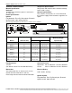
Custom-Engineered, Low-Intensity Infrared Heating Systems Submittal: CRV-Series Job: Location: Engineer: Gas Specs: Date: QTY. MODEL NO. CRV UNIT INPUT BTU/HR QTY. MODEL NO. CRV UNIT INPUT BTU/HR QTY. MODEL NO. CRV UNIT INPUT BTU/HR QTY. MODEL NO. CRV UNIT INPUT BTU/HR TOTAL INPUT BTU/HR Important Before installation and operation of heating equipment, read and understand the Installation, Operation and Service Manual.
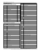
ROBERTS GOR DON® CRV-SE RI ES S UBMI TT AL S HE ET STANDARD PARTS LIST Contents of CRV-Series Burner Carton Part No.
ROBERTS GORDON ® CRV-SE RI ES S UBM ITT AL S HE ET 91903202 Turnbuckle with Eyebolt Thermostats 02712100 Universal Shield Support 05023000 Load Relay Package 02751800 Universal Shield with Holes 90417600 Transformer Relay - SPST (12A) 02751801 Universal Shield 90436300 Transformer Relay - DPDT (12A) 027518SS Universal Shield, Stainless Steel 90423000 24V Low Voltage Thermostat (Marked 1-5) 90424300 Thermostat Guard Control Packages and Accessories BZC700 ROBERTS GORDON® BZC 700 Controller
ROBERTS GOR DON® CRV-SE RI ES S UBMI TT AL S HE ET Pump Packages and Accessories 02719105 EP-100 Pump Package 02719100 EP-100 Pump 02724700 Accessory Package 02716305 EP-201 Pump Package 01312001 EP-201 Pump 01317805 Accessory Package 02712034 EP-203 Pump Package 01312002 EP-203 Pump 01317805 Accessory Package 02723014 EP-301 Pump Package 4" 02730101 EP-301 Pump Assembly 02730104 Accessory Package 02723016 EP-301 Pump Package 6" 02730101 EP-301 Pump Assembly 02730106 Accessory Package P
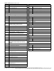
ROBERTS GORDON ® CRV-SE RI ES S UBM ITT AL S HE ET Suspension Specifications GENERAL SPECIFICATIONS Material Specification Reflectors .024 Mill Finish Aluminium (Optional - 024 Stainless Steel Type 304). Hang heater with materials with a minimum working load of 75 lbs (33 kg). Controls Specifications Time switches, thermostats, etc. can be wired into the electrical supply. External controls supplied as an option.
ROBERTS GOR DON® CRV-SE RI ES S UBMI TT AL S HE ET Pump Specifications Pump Dimensional Data (in.) Model A B EP-100 17 14.5 EP-201/203 17.75 17 EP-301 25.6 24.8 C 21 18.75 22.7 D 3.75 3.25 4.8 E 10 10 15.2 F 4 4.5 6 G 4 4.5 6 G A D E B C F dia. Pump Specifications Model EP-100 EP-201 EP-203 EP-301 1/3 3/4 3/4 2* Phase 1 1 3 1 Hertz (Hz) 60 60 60 60 Voltage (V) 115/230 115/230 230 230 Full Load Amp (Amps) 4.8/2.4 6.6/3.3 3.0 11.
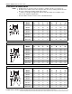
ROBERTS GORDON ® CRV-SE RI ES S UBM ITT AL S HE ET CLEARANCES TO COMBUSTIBLES NOTE: 1. All dimensions are from the surfaces of all tubes, couplings, elbows, tees and crosses. 2. Clearances B, C and D can be reduced by 50% after 25' (7.5 m) of tubing downstream from where the combustion chamber and the tube connect. 3. “-” indicates an unapproved application. Roberts-Gordon prohibits the installation of this heater for all unapproved applications.
ROBERTS GOR DON® CRV-SE RI ES S UBMI TT AL S HE ET NOTE: 1. All dimensions are from the surfaces of all tubes, couplings, elbows, tees and crosses. 2. Clearances B, C and D can be reduced by 50% after 25' (7.5 m) of tubing downstream from where the combustion chamber and the tube connect. 3. “-” indicates an unapproved application. Roberts-Gordon prohibits the installation of this heater for all unapproved applications.
ROBERTS GORDON ® CRV-SE RI ES S UBM ITT AL S HE ET NOTE: 1. All dimensions are from the surfaces of all tubes, couplings, elbows, tees and crosses. 2. Clearances B, C and D can be reduced by 50% after 25' (7.5 m) of tubing downstream from where the combustion chamber and the tube connect. 3. “-” indicates an unapproved application. Roberts-Gordon prohibits the installation of this heater for all unapproved applications.
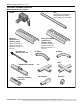
ROBERTS GOR DON® CRV-SE RI ES S UBMI TT AL S HE ET CRV-SERIES ASSEMBLY OVERVIEW Major Component Descriptions Tube Hot Rolled, Heat Treated or Coated Aluminized Tube supplied in 10' (3 m) lengths. Burner Reflector (Aluminum or Stainless Steel) Alternate overlap as shown on overview. Minimum overlap is 7" (18 cm). Flex Gas Line with shut-off cock Reflector with Hole (Aluminum or Stainless Steel) Alternate overlap as shown on overview. Minimum overlap is 7" (18 cm).
ROBERTS GORDON ® CRV-SE RI ES S UBM ITT AL S HE ET Major Component Descriptions (Continued) Reflector Joint Reflector End Cap (Aluminum or Stainless Steel) Remove center section to accommodate heat exchanger tube when necessary. Tube and Reflector Hanger with Clamp Package Position this hanger no more than 4" (10 cm) away from the burner. Tube and Reflector Hanger Suspend system from these hangers.
ROBERTS GOR DON® CRV-SE RI ES S UBMI TT AL S HE ET Major Component Descriptions (Continued) DANGER DANGER Hazard Electrical Shock electrical Disconnect servicing. power before ce must be This applianto a properly connected electrical source. grounded follow these Failure to result can instructionselectrical shock. in death or com www.rg-inc. ue Choc Électriq Danger de le courant Débrancheravant toute électrique révision. il doit être Cet appare à une source de connecter mise á terre.
S Coupling Relay* Exhaust to Outside Reflector with Hole * May not be needed with certain pumps and controllers. Refer to wiring diagram in the appropriate controller Installation, Operation and Service Manual for details. **ROBERTS GORDON® BZC Controllers require zone sensors. System Control requires thermostats. ROBERTS GORDON® ULTRAVAC® requires zone sensors and additional control equipment. See the appropriate controller installation manual for details.
ROBERTS GOR DON® CRV-SE RI ES S UBMI TT AL S HE ET HEATER INSTALLATION Critical Hanger Placement Typical Suspension Details Concrete Beam Beam Clamp Anchor Locknut Wood Beam Screw Hook (3/8") Rod (3/8") 24" min. (61 cm) "X" (see table) Chain size 3/16" minimum Washers Turnbuckle Locknut (Typical) S Hook 7'6" (2.
ROBERTS GORDON ® CRV-SE RI ES S UBM ITT AL S HE ET Tube Installation NOTE: Tubing requires a downward slope of 1/2" (13 mm) per 20' (6 m) away from burner. Tailpipe Tubing requires a downward slope of 1" (26 mm) per 20' (6 m) away from burner.
ROBERTS GOR DON® CRV-SE RI ES S UBMI TT AL S HE ET Coupling and Tube Assembly (Continued) Tighten Slide Bar as shown below. Drive Slide Bar until tight. End of Slide Bar should be within tolerance listed below. ± 2" (5 cm) Correct Slide Bar dimensions Incorrect Slide Bar position Repeat A - D until all tubes are assembled. NOTE: If Coupling is not tight, loss of vacuum can occur.
ROBERTS GORDON ® CRV-SE RI ES S UBM ITT AL S HE ET REFLECTOR INSTALLATION Reflector Installation with Hole Reflector with Hole Slide Reflector with hole through hanger. Unhook combustion chamber from chain and insert through hole. Reconnect chain.
ROBERTS GOR DON® CRV-SE RI ES S UBMI TT AL S HE ET Reflector, U-Clip and Reflector Support Installation The pictorial drawings of the heater construction in this Section are schematic only and provide a general guideline of where hangers, reflector supports and U-clips are to be installed. To ensure proper expansion and contraction movement of the reflectors, a combination of U-clips and reflector supports are used. The positioning of reflec- tor supports and U-clips depend on the individual installation.
ROBERTS GORDON ® CRV-SE RI ES S UBM ITT AL S HE ET Burner Installation Burner Burner Combustion Chamber Gasket End Vent Combustion Chamber Description Bolt Burner Lock Washer Gasket End Vent Part Number 94273914 0270XXXX 96411600 01367800 013676XX End Vent Clips End Vent NOTE: Install End Vent at end combustion chamber position only Rating Number INSTALLATIO N AND OPERATI ON OF HEATIN G EQUI PMENT, READ AND UNDERSTAND THE I NSTALLATION, O PERATION AND SERVICE MANUAL.
ROBERTS GOR DON® CRV-SE RI ES S UBMI TT AL S HE ET OPTIONAL HEATER ACCESSORIES Tee Installation Tube Coupling Tee Description Tee Tube/Reflector Hanger Tube Coupling Part Num ber 01330XXX 03090100 91409XXX 01312700 Reflector Joint Installation Reflector Reflector Joint Flatten Edge Scribe Contour 1" (2.5 cm) maximum IN STALLATI ON AND OPER ATI ON OF HEATI NG EQUIPMENT, READ AND U NDERSTAND THE INSTALLATION, OPERATIO N AND SERVICE MANUAL.
ROBERTS GORDON ® CRV-SE RI ES S UBM ITT AL S HE ET Reflector Joint Installation (continued) Cut away contour with tin snips. Punch/Drill six 3/32" (2 mm) holes Reflector Joint Detail Install Reflector End Cap Attach Reflector Joint with six #8 sheet metal screws Reflector Joint Detail Reflector Reflector Joint INSTALLATIO N AND OPERATI ON OF HEATIN G EQUI PMENT, READ AND UNDERSTAND THE I NSTALLATION, O PERATION AND SERVICE MANUAL.
ROBERTS GOR DON® CRV-SE RI ES S UBMI TT AL S HE ET REFLECTOR SIDE EXTENSION Bracket Installation Tube Reflector Tube and Reflector Hanger Reflector Support Reflector Side Extension Bracket (2 per reflector) Use additional supports in high air movement applications.
ROBERTS GORDON ® CRV-SE RI ES S UBM ITT AL S HE ET Universal Shield Universal shields are adjustable aluminum reflectors that can be angled and height adjusted to direct heat to or away from a desired area.
ROBERTS GOR DON® CRV-SE RI ES S UBMI TT AL S HE ET TWO-FOOT DECORATIVE GRILLE INSTALLATION Grille Installation Tube and Reflector Hanger Reflector Heat Exchanger Tube 2' x 4' (60 x 120 cm) Aluminum Grille Suspended Ceiling Frame Description Aluminium Grille 2' x 4' Par t Number 91407000 Description Deco Grille Shield Par t Number 01365900 Frame Shield Installation Shield IN STALLATI ON AND OPER ATI ON OF HEATI NG EQUIPMENT, READ AND U NDERSTAND THE INSTALLATION, OPERATIO N AND SERVICE MANUAL.
ROBERTS GORDON ® CRV-SE RI ES S UBM ITT AL S HE ET Reflector Side Extension Installation for Decorative Grilles NOTE: If the Decorative Grille system is to be installed in an area with considerable air movement, it is recommended that one #8 x 3/8 (3.9 x 9.5mm) sheet metal screw be installed per reflector 6" (15 cm) Minimum extension to prevent it from blowing over. Cut Relief Notches for Tube and Reflector Hangers Allow 6" (15 cm) minimum clearance between Burner Box and overhead obstructions for service.
ROBERTS GOR DON® CRV-SE RI ES S UBMI TT AL S HE ET Decorative Grille Spread apart brackets and install Decorative Grille. Description Decorative Grille 8’ x 1’ Part Number 91406700 Joint Piece and Reinforcement Joint Piece Slip joint piece into support bracket and fasten to bracket on one side of the joint only.
ROBERTS GORDON ® CRV-SE RI ES S UBM ITT AL S HE ET End Piece and Reflector End Cap Reflector End Cap End Piece Insert end piece between grille and brackets. Fasten end piece to brackets using two #8 sheet metal screws and replace reflector end cap. Descr iption End Piece Part Number 01365901 90° Elbow Inside Corner Grille Brackets Joint Piece Insert End Piece between grille and brackets. Decorative Grille Brackets Cut grille bracket at reflector joint piece.
ROBERTS GOR DON® CRV-SE RI ES S UBMI TT AL S HE ET PROTECTIVE GRILLE INSTALLATION Silicone Cap Installation Silicone Cap Description Grille Section Grille End Cap Silicone Cap Grille Finger Part Number 08050001 08050002 91915951-6P Grille End Cap Installation B A Grille Grille End Cap C D Bend up 90° Pull outward Grille Installation Reflector 40 " (101 cm) Grille Final Grille Section Grille End Cap IN STALLATI ON AND OPER ATI ON OF HEATI NG EQUIPMENT, READ AND U NDERSTAND THE INSTALLATION, O
ROBERTS GORDON ® CRV-SE RI ES S UBM ITT AL S HE ET CRV-Series Classic Cast-Iron Components WARNING Suspension Hazard Hang heater with materials with a minimum working load of 750 lbs. (340 kg). Use special tube and reflector hangers when suspending the schedule 40 steel pipe system. Schedule 40 steel pipe is heavy and will fall if not supported properly. Distance between supports must be 7' (2.13 m) or less. Failure to follow these instructions can result in death, injury or property damage.
ROBERTS GOR DON® CRV-SE RI ES S UBMI TT AL S HE ET PUMP INSTALLATION EP-200 Condensate Valve Assembly Wall 1" BSP threaded hole. Use 1" x ¾" reducer. (not supplied) Copper or galvanized pipe 36" Minimum vertical drop between pump and condensate valve assembly. 3/4" female Condensate Valve Assembly flow 3/4" female Must be connected to a drain system in accordance with local codes.
ROBERTS GORDON ® CRV-SE RI ES S UBM ITT AL S HE ET VENTING Vertical Venting Configuration Approved Vent Cap 2' (610 mm) Minimum Approved Thimble Flexible Boot Aluminized Tee Clamps 1" (250 mm) P.V.C to drain system in accordance with local codes.
ROBERTS GOR DON® CRV-SE RI ES S UBMI TT AL S HE ET EP-200 Series Horizontal Venting Configurations 18" (46 cm) Minimum 40" (102 cm) Maximum Bird Screen 4" (10 cm) Single Wall Pipe 10' (3 m) Maximum and No Elbows Approved Thimbles 18" (46 cm) Minimum 40" (102 cm) Maximum 4" (10 cm) Vent Terminal Vent Terminal Tjernlund VH1-4 6" to 5" Reducer (15 cm to 12.5 cm) 5" to 4" Reducer (12.5 cm to 10 cm) 5" (12.
ROBERTS GORDON ® CRV-SE RI ES S UBM ITT AL S HE ET OUTSIDE COMBUSTION AIR SUPPLY Filter Housing Assembly Door-Control Housing Filter Filter Support Bottom Gasket Filter Housing Top Gasket and Disk Wing Nut 4" (10 cm) Air Flex Duct Description Filter Housing Filter and Gaskets Filter Support Wing Nut 4” Air Flex Duct (box of eight 8’ sections) Clamp Part Number 01326801 01312401 91905500 92511601 91409601 Air Supply Blower Support Outside Air Supply Blower Description Blower Mounting Bracket Par
ROBERTS GOR DON® CRV-SE RI ES S UBMI TT AL S HE ET Pressurized Outside Air Supply Outside Air Supply Blower Description Filter Housing 4" Take Off Blower Par t Number 01326801 01324401 90707501 Description Pressure Switch Kit 4" Bird Screen 4" Vent Cap 6" Vent Cap Par t Number 90434501 01365400 90502300 90502302 Burner Filter Housing 4" (10 cm) Air Flex Duct Mounting Bracket 4" (10 cm) Take Off Clamp Outside Wall Sheet Metal or PVC Non-Pressurized Outside Air Supply Vent Cap Pressure Switch
ROBERTS GORDON ® CRV-SE RI ES S UBM ITT AL S HE ET GAS PIPING Gas Connection with Stainless Steel Flex Gas Connector Shut-Off Valve must be parallel to burner gas inlet. The 2" (50 mm) displacement shown is for the cold condition. This displacement may reduce when the system is fired. Description 1/2" Flex Gas Line 3/4" Flex Gas Line Part Number 91412200 91412203 Hold gas nipple securely with pipe wrench when attaching the flex gas connector.
ROBERTS GOR DON® CRV-SE RI ES S UBMI TT AL S HE ET WIRING One Zone Operation without Control Panel SPST (12A) Transformer Relay WARNING R Electrical Shock Hazard W G Disconnect electrical power and gas supply before servicing. Y Thermostat This appliance must be connected to a properly grounded electrical source. Failure to follow these instructions can result in death or electrical shock.
ROBERTS GORDON ® CRV-SE RI ES S UBM ITT AL S HE ET Two Zone Operation without Control Panel DPST (12A) Transformer Relay DPST (12A) Transformer Relay R W G C R C W G Y Zone 1 Thermostat Y Zone 2 Thermostat Purple 1 4 COIL Red 1 3 2 6 COIL 5 Purple Red 2 4 COIL 5 3 6 COIL Black 120V 1ph 60Hz Black Black Red/Yellow White White L Red/Yellow Black N L L L N N Pump Motor Pressure Switch (Pump) N Zone 1 Burners Zone 2 Burners Nine Burners Total Maximum Between Zones Descript
ROBERTS GOR DON® CRV-SE RI ES S UBMI TT AL S HE ET CRV-Series Burner Internal Wiring TRANSFORMER White Black 120 V Power Supply Green Green GAS VALVE 1 5 3 4 Yellow Blue Yellow TH Brown Yellow V1 S1 V2/GND Black IGNITION MODULE BURNER If any of the original wire as supplied with the heater must be replaced, it must be replaced with wiring material having a temperature rating of at least 105°C and 600 volts.
ROBERTS GORDON ® CRV-SE RI ES S UBM ITT AL S HE ET INTERNAL BURNER DIAGRAM Gasket (Burner to Mixing Chamber) Transformer OFF ON Burner Head Mixing Chamber Ignition Module Regulator Electrode Electrode Gasket Combustion Chamber Gasket Gas Valve INSTALLATIO N AND OPERATI ON OF HEATIN G EQUI PMENT, READ AND UNDERSTAND THE I NSTALLATION, O PERATION AND SERVICE MANUAL.
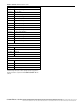
ROBERTS GOR DON® CRV-SE RI ES S UBMI TT AL S HE ET THE ROBERTS GORDON® CORAYVAC® LIMITED WARRANTY ROBERTS-GORDON WILL PAY FOR: The data plate and/or serial number are removed, Within 42 months from date of shipment from RobertsGordon, replacement parts will be provided free of charge for any part of the controller which fails due to a manufacturing or material defect. Roberts-G ordon will require the part in question to be returned to the factory.