FOR YOUR SAFETY If you smell gas: 1. Open windows. 2. DO NOT try to light any appliance. 3. DO NOT use electrical switches. 4. DO NOT use any telephone in your building. 5. Extinguish any open flame. 6. Leave the building. 7. Immediately call your local gas supplier after leaving the building. Follow the gas supplier’s instructions. 8. If you cannot reach your gas supplier, call the Fire Department.
TABLE OF CONTENTS SECTION 1: Heater Safety...................................................... 1 1.1 Manpower Requirements ............................................. 1 1.2 Safety Labels and Their Placement ............................. 1 1.3 California Proposition 65 .............................................. 1 SECTION 2: Installer Responsibility ..................................... 4 2.1 Wall Tag ....................................................................... 4 2.2 Corrosive Chemicals....
TABLE OF FIGURES Figure 1: Top and Bottom Panel Label Placement .................... 2 Figure 2: Side and Back Panel Label Placement ...................... 3 Figure 3: Standard Reflector ..................................................... 5 Figure 4: One Side Reflector..................................................... 6 Figure 5: Two Side Reflectors ................................................... 6 Figure 6: 45° Tilt Reflector ........................................................
SECTION 1: HEATER SAFETY SECTION 1: HEATER SAFETY Your Safety is Important to Us! This symbol is used throughout the manual to notify you of possible fire, electrical or burn hazards. Please pay special attention when reading and following the warnings in these sections. Installation, service and annual inspection of heater must be done by a contractor qualified in the installation and service of gas-fired heating equipment. 1.
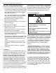
CTH2-SERIES INSTALLATION, OPERATION AND SERVICE MANUAL FIGURE 1: Top and Bottom Panel Label Placement Logo Label Rating Plate Label Bottom Panel Description Logo Label Rating Plate Label Gas Connection Label Proposition 65 Label Part Number 91013200 91010401 91018122 91070015 Proposition 65 Label Top Panel Gas Connection Label 2
SECTION 1: HEATER SAFETY FIGURE 2: Side and Back Panel Label Placement Control Side Panel Clearances to Combustibles Label Control Side Panel (Inside) Wiring Label Vent Length Label Thermostat Connection Label Back Panel Lighting Instruction Plate Label Description Clearances to Combustibles Label Wiring Label Low Voltage Connection Label Vent Length Label Lighting Instruction Plate Label Part Number 91013415 91013300 91039700 91039500 91029602 3
CTH2-SERIES INSTALLATION, OPERATION AND SERVICE MANUAL on the burner and in the Installation, Operation and Service Manual. See Page 5, Figure 3 through Page 8, Figure 12. Write the proper clearance dimensions • To install the heater, as well as the gas and electriin permanent ink according to your model number cal supplies, in accordance with applicable specifi- and configuration in the open spaces on the tag. cations and codes.
SECTION 3: CLEARANCES TO COMBUSTIBLES SECTION 3: CLEARANCES TO COMBUSTIBLES 3.1 Required Clearances to Combustibles WARNING Clearances are the required distances that combustible objects must be away from the heater to prevent serious fire hazards. Combustibles are materials that may catch on fire and include common items such as wood, paper, rubber, fabric, etc. Maintain clearances to combustibles at all times for safety.
CTH2-SERIES INSTALLATION, OPERATION AND SERVICE MANUAL NOTE: 1. All dimensions are from the surfaces of all tubes, couplings and elbows. 2. Clearances B, C and D can be reduced by 50% after 25' (7.5 m) of tubing downstream from where the burner and burner tube connect.
SECTION 3: CLEARANCES TO COMBUSTIBLES NOTE: 1. All dimensions are from the surfaces of all tubes, couplings and elbows. 2. Clearances B, C and D can be reduced by 50% after 25' (7.5 m) of tubing downstream from where the burner and burner tube connect.
CTH2-SERIES INSTALLATION, OPERATION AND SERVICE MANUAL NOTE: 1. All dimensions are from the surfaces of all tubes, couplings and elbows. 2. Clearances B, C and D can be reduced by 50% after 25' (7.5 m) of tubing downstream from where the burner and burner tube connect.
SECTION 4: NATIONAL STANDARDS AND APPLICABLE CODES SECTION 4: NATIONAL STANDARDS AND APPLICABLE CODES 4.1 Gas Codes The type of gas appearing on the nameplate must be the type of gas used. Installation must comply with national and local codes and requirements of the local gas company. United States: Refer to National Fuel Gas Code NFPA 54/ANSI Z223.1 - latest revision. Canada: Refer to Natural Gas and Propane Installation Code CSA B149.1 - latest revision. 4.
CTH2-SERIES INSTALLATION, OPERATION AND SERVICE MANUAL SECTION 5: MAJOR COMPONENTS FIGURE 13: Major Component Descriptions Burner with Tube Gasket Must be installed with the flame observation window facing down. Burner Tube Supplied in 10' (3 m) lengths. Burner tube is always the first tube after the burner. Tube and Reflector Hanger with Clamp Package Position this hanger no more than 4" (10 cm) away from the burner. Tube and Reflector Hanger Suspend system from these hangers.
SECTION 5: MAJOR COMPONENTS 5.1 Standard Parts List Table 1: Contents of the Burner Carton Part No.
CTH2-SERIES INSTALLATION, OPERATION AND SERVICE MANUAL Table 3: Component Package Guide Model Tubing Length Core Packages Minimum Standard Aluminized CTH2-40 10’ (3m) - CP10ALUM CTH2-60 20’ (6m) CP20HRS CP20ALUM CTH2-80 20’ (6m) CP20HRS CP20ALUM CTH2-100 30’ (9m) CP30HRS CP30ALUM CTH2-125 40’ (12m) CP40HRS CP40ALUM CTH2-150 50’ (15m) CP30HRS + EXP20HRS CP30ALUM + EXP20ALUM CTH2-175 60’ (18m) CP30HRS + EXP30HRS CP30ALUM + EXP30ALUM Additional tubing length may be added to h
SECTION 6: HEATER INSTALLATION SECTION 6: HEATER INSTALLATION WARNING Typical installation configurations are shown in Figure 14. Expansion and contraction of the tube dictates that the minimum suspension lengths in the table on Page 14, Figure 14 be maintained. Severe Injury Hazard Secure burner to burner tube with bolts and lockwashers. Hang heater with materials with a minimum working load of 75 lbs (33 kg). Failure to follow these instructions can result in death, injury or property damage.
CTH2-SERIES INSTALLATION, OPERATION AND SERVICE MANUAL FIGURE 14: Critical Hanger Placement Typical Suspension Details Beam Clamp Anchor Screw Hook 3/8" 24" min.
Reflector Support Tube and Reflector Hanger Coupling Burner Tube Tube Clamp Package Burner Reflector End Cap Reflector Vent Adapter Tube Turbulator (With Select Models) U-Clips SECTION 6: HEATER INSTALLATION FIGURE 15: Linear Heater Assembly Overview 15
CTH2-SERIES INSTALLATION, OPERATION AND SERVICE MANUAL FIGURE 16: Linear Heater Layout Overview LEGEND g b c d Burner Reflector f 10' Tube Length Tube Tube/Reflector Hanger Coupling Assembly g b c d e Vent Adapter a = 14" (36 cm) reflector width (not shown) f b = 2" (5 cm) end cap to burner 20' Tube Length c = 2" (5 cm) end cap to hanger d = 7'6" (229 cm) distance first hanger g b c d e e e = 10' (305 cm) distance between hangers f = 9.5" (24 cm) burner height f g = 17.
SECTION 6: HEATER INSTALLATION FIGURE 17: Linear Heater Layout Overview (Continued) g b c d e e e e e e e e e e e e e e e e e e f 50' Tube Length g b c d e f 60' Tube Length g b c d e b f 70' Tube Length g b c d e e b f 80' Tube Length 17
CTH2-SERIES INSTALLATION, OPERATION AND SERVICE MANUAL Step 6.1 Burner Tube Installation NOTE: Tubing requires a downward slope of 1/2" (1.3 cm) per 20' (6 m) away from burner. Offset mounting hole must be to the top. S-hook Hanger Burner Tube Weld seam must be to the bottom of the tube. 7' 6" ± 1' (229 cm ± 25 cm) Description Burner Tube S-Hook Tube/Reflector Hanger Part Number 03051XXX 91907302 03090100 Step 6.2 Tube Clamp Package Installation Tube Clamp Flat Washer Nut (Torque 120 in/lb 13.
SECTION 6: HEATER INSTALLATION Step 6.3 Coupling and Tube Assembly Close coupling A with tab. Start Slide bar/Coupling Lock B onto coupling. Tab Slide Bar/Coupling Lock Wide End Coupling Open 3" (8 cm) to 4" (10 cm) Closed C Insert tubes into coupling. D Tighten coupling to join tubes. Slide Bar/Coupling Lock Coupling Orient coupling so that the impact block is in the 2:00 or 10:00 oclock positions.
CTH2-SERIES INSTALLATION, OPERATION AND SERVICE MANUAL Step 6.3.2 Coupling and Tube Assembly (Continued) Model CTH2-40 CTH2-60 CTH2-80 CTH2-100 CTH2-125 CTH2-150 CTH2-175 Tube Length Minimum 10' (3 m) 20' (6 m) 20' (6 m) 30' (9 m) 40' 12 m) 50' (15 m) 60' (18 m) 7' 6" ± 1' (2.3 m ± .25 m) 10' ± 1' (3 m ± .25 m) Total Overall Tube Length Step 6.4 Turbulator Installation Turbulator must be installed in the last standard section of tube. Turbulator is not required on the CTH2-125/150/175.
SECTION 6: HEATER INSTALLATION Step 6.5 Reflector Installation WARNING Fire Hazard Support reflector with reflector hanger and support strap. Reflector must not touch tube. Failure to follow these instructions can result in death, injury or property damage. NOTE: All tube surfaces must be covered by a reflector, except for a U-Tube.
CTH2-SERIES INSTALLATION, OPERATION AND SERVICE MANUAL Step 6.5.1 Reflector, U-Clip and Reflector Support Installation The pictorial drawings of the heater construction in Section 6 are schematic only and provide a general guideline of where hangers, reflector supports and U-clips are to be installed. To ensure proper expansion and contraction movement of the reflectors, a combination of U-clips and reflector supports are used.
SECTION 6: HEATER INSTALLATION Step 6.6 Burner Installation Burner Gasket S-hook Burner Tube Burner must be installed with the flame observation window facing down. Description Bolt Burner Lock Washer Gasket Part Number 94273914 030XXXXX 96411600 02568200 Lock Washer Bolt (Torque 120 in/lb 13.
CTH2-SERIES INSTALLATION, OPERATION AND SERVICE MANUAL SECTION 7: OPTIONAL HEATER ACCESSORIES WARNING Cut/Pinch Hazard Wear protective gear during installation, operation and service. Edges are sharp. Failure to follow these instructions can result in injury. 7.1 U-Tube Configuration Heaters (except CTH2-40) are approved for optional U-Tube configurations.
SECTION 7: OPTIONAL HEATER ACCESSORIES FIGURE 18: U-Tube Heater Assembly Overview 25
CTH2-SERIES INSTALLATION, OPERATION AND SERVICE MANUAL FIGURE 19: U-Tube Heater Layout Overview LEGEND g Burner b c e Reflector Tube 10' h Tube 5' ** 20' Tube Length* Tube/Reflector Hanger Coupling Assembly g U-Tube b c d f a = 14" (36 cm) reflector width (not shown) b = 2" (5 cm) end cap to burner h 30' Tube Length** c = 2" (5 cm) end cap to hanger d = 7'6" (229 cm) distance first hanger e = 10' (305 cm) distance between hangers g b c d f = 5' (153 cm) distance between last full tube
SECTION 7: OPTIONAL HEATER ACCESSORIES FIGURE 20: U-Tube Heater Layout Overview (Continued) g b c d e f h 50' Tube Length* ** g b c d e e e e e e h 60' Tube Length g b c d f h 70' Tube Length** g b c d e h 80' Tube Length 27
CTH2-SERIES INSTALLATION, OPERATION AND SERVICE MANUAL 7.2 Elbow Package Configuration Step 7.2.1 Elbow Installation Tube Coupling Description Elbow Package 90° Elbow Coupling Reflector End Cap Reflector Joint Piece U-Clip Package Part Number 02718702 01335801 01312700 02750800 02750900 91107720 90° Elbow Minimum Distance Required Between Burner and Elbow Model Minimum Distance CTH2-40 CTH2-60 10' (3 m) CTH2-80 10' (3 m) CTH2-100 15' (4.5 m) CTH2-125 15' (4.5 m) CTH2-150 15' (4.5 m) CTH2-175 15' (4.
SECTION 7: OPTIONAL HEATER ACCESSORIES Step 7.2.4 Reflector Joint Installation Step 7.2.
CTH2-SERIES INSTALLATION, OPERATION AND SERVICE MANUAL 7.3 Reflector Side Extension Step 7.3.1 Bracket Installation Tube Reflector Tube and Reflector Hanger Reflector Support Reflector Side Extension Bracket (2 per Reflector) Use additional supports in high air movement applications. Description Reflector Side Extension Package Reflector Side Extension Retainer Clips Sheet Metal Screws Order Separately Reflector Side Extension Part Number 02712700 01368000 02751200 94118106 01329910 Step 7.3.
SECTION 7: OPTIONAL HEATER ACCESSORIES 7.4 Lower Clearance Shield Installation Step 7.4.1 Shield Support Strap Assembly Reflector 17" (43 cm) 12" (30 cm) Align Pilot Holes Lower Clearance Shield Locknuts Washers Screws Description Lower Clearance Shield Package Shield Support Strap Lower Clearance Shield 8' Locknut #8 Flat Washer #8 Screw #8 x 3/8" Part Number 01397501 01397500 02793000 92311400 95310800 93511406 Description Aluminum Grille 2' x 4' (.6m x 1.2 m) Part Number 91407000 7.
CTH2-SERIES INSTALLATION, OPERATION AND SERVICE MANUAL Step 7.5.2 Frame Shield Installation Description Deco Grille Shield Part Number 01365900 Step 7.5.3 Reflector Side Extension Installation for Decorative Grilles Distance "A" Minimum Maximum 2" (4 cm) 6" (15 cm) 6" (15 cm) 10" (26 cm) 10" (26 cm) 14" (37 cm) 32 Extension Part No.
SECTION 7: OPTIONAL HEATER ACCESSORIES 7.6 Protective Grille Installation Step 7.6.1 Silicone Cap Installation Silicone Cap Description Grille Section Grille End Cap Silicone Cap Grille Finger Part Number 08050001 08050002 91915951-6P Step 7.6.2 Grille End Cap Installation B A Grille Grille End Cap C D Bend up 90°. Pull outward. Step 7.6.
CTH2-SERIES INSTALLATION, OPERATION AND SERVICE MANUAL SECTION 8: VENTING WARNING Carbon Monoxide Hazard Heaters installed unvented must be interlocked with sufficient building exhaust. Heaters must be installed according to the installation manual. Failure to follow these instructions can result in death or injury. WARNING Vent pipe must be sloped downward away from the burner 1/2'' (1 cm) for every 20' (6 m). The heater may be individually vented or common vented.
SECTION 8: VENTING 8.3 Horizontal Venting In noncombustible walls only, vent terminal (P/N 02537801-1P) may be used. FIGURE 22: Tube Termination For 4'' (10 cm) vents in either combustible or noncombustible walls, use Tjernlund VH1-4 (P/N 90502100) or equivalent insulated vent terminal. Follow the manufacturer's instructions for proper installation. For 6'' (15 cm) common vents in either combustible or noncombustible walls, use Tjernlund VH1-6 (P/N 90502101) or equivalent insulated vent terminal.
CTH2-SERIES INSTALLATION, OPERATION AND SERVICE MANUAL 8.8 Vertical Ventilation 4" (10 cm) Pipe Description Vent Cap 4" (10 cm) Part Number 90502300 Step 8.
SECTION 8: VENTING 8.10 Common Vertical Venting Requirements: • Maximum of four heaters can be commonly vented through the roof. • Heaters must be of the same BTU output. • Heaters must be controlled by a common thermostat. • Connections to a common stack must be positioned to avoid direct opposition between streams of combustion gases.
CTH2-SERIES INSTALLATION, OPERATION AND SERVICE MANUAL 8.11 Outside Combustion Air Supply mended with unvented heaters. IMPORTANT: If the building has a slight negative pressure or corrosive contaminants, such as halogenated hydrocarbons, are present in the air, an outside combustion air supply to the heater is required. Seal all combustion air pipe joints. The air supply duct may have to be insulated to prevent condensation on the outer surface.
SECTION 8: VENTING 8.11.4 Vertical Outside Air Supply for Double Heater Installation Vent Cap Roof 6" (15 cm) Single Wall Pipe Flex Hose (Recommended) Burner Band Clamp (Recommended) Description Vent Cap 6" (15 cm) Sweeping 'T' Connection Burner Flex Hose (Recommended) 4" (10 cm) Single Wall Pipe Part Number 90502302 Requirements: • Heaters must be controlled by a common thermostat. 8.11.
CTH2-SERIES INSTALLATION, OPERATION AND SERVICE MANUAL SECTION 9: GAS PIPING WARNING Fire Hazard Tighten gas hose fittings to connect gas supply according to Figure 23. Gas hose can crack when twisted. Gas hose moves during normal operation. Use only 36" (91 cm) long connector of 1/2" or 3/4" nominal ID. Connector supplied with heater for U.S. models (not with Canadian models). Failure to follow these instructions can result in death, injury or property damage.
SECTION 9: GAS PIPING FIGURE 23: Gas Connection with Flexible Gas Hose CORRECT POSITIONS CAUTION Product Damage Hazard Shut-Off Valve (included with gas hose) must be parallel to burner gas inlet. The 3" (8 cm) displacement shown is for the cold condition. This displacement may reduce when the system is fired. Hold gas nipple securely with pipe wrench when attaching gas hose. Failure to follow these instructions can result in product damage. Vertical (as shown left) 12" (30 cm) 3" (8 cm) max.
CTH2-SERIES INSTALLATION, OPERATION AND SERVICE MANUAL SECTION 10: WIRING DANGER Electrical Shock Hazard Disconnect electric before service. Heater must be properly grounded. Failure to follow these instructions can result in death or electrical shock. Heaters can be controlled using several methods. Normally thermostats are used to control the heaters but they can also be controlled by an Energy Management System. Section 10.
SECTION 10: WIRING 10.3 Low Voltage Thermostat Wiring with Multiple Burners FRONT VIEW Transformer Relay BACK VIEW Low Voltage Thermostat 1 2 4 Black R 3 COIL 5 C 6 COIL W G Y Purple Black White Burner 1 Red Burner 2 Low Voltage Terminal Detail on all Burners 120V-60 Hz supply circuit Gnd. H Gnd. N H N L1 L2 Burner 3 Gnd. When using 1-2 burners, use SPST Transformer Relay. When using 3-4 burners, use SPDT Transformer Relay. Burner 4 Gnd. Red/Yellow H Gnd. N H N 10.
CTH2-SERIES INSTALLATION, OPERATION AND SERVICE MANUAL 10.5 Ladder Diagram L2 L1 TRANSFORMER WHITE BLACK ORANGE BLUE VALVE WHITE TO THERMOSTAT PRESSURE SWITCH YELLOW YELLOW PURPLE HOT SURFACE IGNITER WHITE WHITE WHITE BLACK DOOR SWITCH GREY FLAME SENSOR MOTOR WHITE BLACK 10.6 Electrical Connection to the Burner Electrical Cord or Flexible Conduit BX or Romex Connector Burner 44 Connect wires together with suitable approved wire connectors.
SECTION 11: OPERATION AND MAINTENANCE SECTION 11: OPERATION AND MAINTENANCE WARNING DANGER Electrical Shock Hazard Disconnect electric before service. Explosion Hazard Turn off gas supply to heater before service. Heater must be connected to a properly grounded electrical source. Burn Hazard Allow heater to cool before service. Cut/Pinch Hazard Wear protective gear during installation, operation and service. Tubing may still be hot Edges are sharp. after operation.
CTH2-SERIES INSTALLATION, OPERATION AND SERVICE MANUAL service or maintenance. Allow heater to cool before servicing. Before every heating season, a contractor qualified in the installation and service of gas-fired heating equipment must perform a thorough safety inspection of the heater. For best performance, the gas, electrical, thermostat connections, tubing, venting, suspensions and overall heater condition should be thoroughly inspected.
SECTION 11: OPERATION AND MAINTENANCE Gas Line Burner Observation Window Blower Scroll, Wheel and Motor Burner Cup and Orifice Hot-Surface Igniter Thermostat Check for gas leaks. See Page 40, Section 9. Make sure it is clean and free of cracks or holes. Clean and replace as required. Compressed air or a vacuum cleaner may be used to clean dust and dirt. Clear of obstructions (even spider webs will cause problems). Carefully remove any dust and debris from the burner. Replace if cracked or broken.
CTH2-SERIES INSTALLATION, OPERATION AND SERVICE MANUAL SECTION 12: TROUBLESHOOTING DANGER Electrical Shock Hazard Disconnect electric before service. Heater must be properly grounded. Failure to follow these instructions can result in death or electrical shock. WARNING Fire Hazard Keep all flammable objects, liquids and vapors the minimum required clearances to combustibles away from heater. Explosion Hazard Turn off gas supply to heater before service.
SECTION 12: TROUBLESHOOTING 12.1 Honeywell SmartValve® II Troubleshooting This heater is supplied with the Honeywell SmartValve® II control system. This system is equipped with a diagnostic function that will assist in performing troubleshooting. The LED (Light Emitting Diode) indicator at the top of the SmartValve® II control will flash in various patterns to indicate status. The LED status indication chart provided below gives a summary of possible faults.
CTH2-SERIES INSTALLATION, OPERATION AND SERVICE MANUAL 12.
SECTION 12: TROUBLESHOOTING 51
CTH2-SERIES INSTALLATION, OPERATION AND SERVICE MANUAL 12.3 Manifold Gas Pressure Setting Orifice Top View of Heater Manometer 6 5 4 3 2 1 0 1 2 3 4 5 6 Natural 52 3.5" 6 5 4 3 2 1 0 1 2 3 4 10.
SECTION 13: REPLACEMENT PARTS SECTION 13: REPLACEMENT PARTS WARNING DANGER Electrical Shock Hazard Explosion Hazard Fire Hazard Carbon Monoxide Hazard Use only genuine ROBERTS GORDON® replacement parts per this installation, operation and service manual. Failure to follow these instructions can result in death, electric shock, injury or property damage.
CTH2-SERIES INSTALLATION, OPERATION AND SERVICE MANUAL Motor and Blower Assembly Blower Inlet Gasket Door Switch Burner Cup Assembly Mica Window Assembly Orifice Air Adapter Collar Gas Valve Hot Surface Igniter Pressure Switch SmartValve R II Flame Sensor Jumper Wire Tube Gasket Thermostat Connection Transformer 54
SECTION 13: REPLACEMENT PARTS Description Gas Valve (Natural) Gas Valve (LP) Tube Gasket Blower Inlet Gasket Motor and Blower Assembly Air Adapter Collar Door Switch Burner Cup Assembly Hot Surface Igniter Mica Window Assembly Flame Sensor Transformer Thermostat Connection Jumper Wire Pressure Switch: (175) (100) (80,150) (40, 60, 125) Part Number 90068300 90068302 02568200 03050900 90708600-P 91911700 90436800 03020100 90436603K 02553203 90439300 90436900K 91317900 03090900 90439802K 90439803K 90439810K
CTH2-SERIES INSTALLATION, OPERATION AND SERVICE MANUAL SECTION 14: GENERAL SPECIFICATIONS 14.1 Material Specifications 14.1.1 Reflectors 14.3 Suspension Specifications .024 Aluminum (optional .024 Stainless Steel Type 304) 14.4 Controls Specifications Hang heater with materials with a minimum working load of 75 lbs (33 kg). See Page 14, Figure 14. Time switches, thermostats, etc. can be wired into the electrical supply. External controls supplied as an optional extra. 14.2 Heater Specifications 14.2.
SECTION 15: THE ROBERTS GORDON® VANTAGE® II WARRANTY SECTION 15: THE ROBERTS GORDON® VANTAGE® II WARRANTY Roberts-Gordon is not permitted to inspect the damaged ROBERTS-GORDON WILL PAY FOR: Within 36 months from date of purchase by buyer or 42 months from date of shipment by Roberts-Gordon LLC (whichever occurs first), replacement parts will be provided free of charge for any part of the product which fails due to a manufacturing or material defect.