FOR YOUR SAFETY If you smell gas: 1. Open windows. 2. DO NOT try to light any appliance. 3. DO NOT use electrical switches. 4. DO NOT use any telephone in your building. 5. Leave the building. 6. Immediately call your local gas supplier after leaving the building. Follow the gas suppliers instructions. 7. If you cannot reach your gas supplier, call the Fire Department.
TABLE OF CONTENTS SECTION 1: Heater Safety...................................................... 1 1.1 Manpower Requirements ............................................. 1 SECTION 2: Installer Responsibility ..................................... 2 2.1 Wall Tag ....................................................................... 2 2.2 Corrosive Chemicals.................................................... 2 2.3 National Standards and Applicable Codes ..................
TABLE OF FIGURES Figure 1: Standard Reflector ..................................................... 3 Figure 2: One Side Reflector..................................................... 4 Figure 3: Two Side Reflectors ................................................... 4 Figure 4: 45° Tilt Reflector ........................................................ 4 Figure 5: U-Tube, Standard Reflector........................................ 5 Figure 6: U-Tube, 45° .....................................................
SECTION 1: HEATER SAFETY SECTION 1: HEATER SAFETY Your Safety is Important to Us! This symbol is used throughout the manual to notify you of possible fire, electrical or burn hazards. Please pay special attention when reading and following the warnings in these sections. Installation, service and annual inspection of heater must be done by a contractor qualified in the installation and service of gas-fired heating equipment.
CTHN-SERIES INSTALLATION, OPERATION AND SERVICE MANUAL SECTION 2: INSTALLER RESPONSIBILITY The installer is responsible for the following: • To install the heater, as well as the gas and electrical supplies, in accordance with applicable specifications and codes. Roberts-Gordon recommends the installer contact a local Building Inspector or Fire Marshal for guidance.
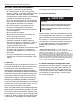
SECTION 3: CRITICAL CONSIDERATIONS SECTION 3: CRITICAL CONSIDERATIONS 3.1 Required Clearances to Combustibles WARNING Clearances are the required distances that combustible objects must be away from the heater to prevent fire hazards. Combustible materials that may catch fire include common items such as wood, paper, rubber, fabric, etc. Maintain clearances to combustibles at all times for safety.
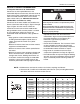
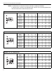
CTHN-SERIES INSTALLATION, OPERATION AND SERVICE MANUAL NOTE: 1. All dimensions are from the surfaces of all tubes, couplings and elbows. 2. Clearances B, C and D can be reduced by 50% after 25' (7.5 m) of tubing downstream from where the burner and burner tube connect. .
SECTION 3: CRITICAL CONSIDERATIONS NOTE: 1. All dimensions are from the surfaces of all tubes, couplings and elbows. 2. Clearances B, C and D can be reduced by 50% after 25' (7.5 m) of tubing downstream from where the burner and burner tube connect.
CTHN-SERIES INSTALLATION, OPERATION AND SERVICE MANUAL NOTE: 1. All dimensions are from the surfaces of all tubes, couplings and elbows. 2. Clearances B, C and D can be reduced by 50% after 25' (7.5 m) of tubing downstream from where the burner and burner tube connect.
SECTION 4: NATIONAL STANDARDS AND APPLICABLE CODES SECTION 4: NATIONAL STANDARDS AND APPLICABLE CODES 4.1 Gas Codes The type of gas appearing on the nameplate must be the type of gas used. Installation must comply with national and local codes and requirements of the local gas company. United States: Refer to National Fuel Gas Code, ANSI Z223.1 - latest revision (same as NFPA 54). Canada: Refer to CAN/CGA B149.1 and B149.2: Installation Codes for Gas Burning Appliances. 4.
CTHN-SERIES INSTALLATION, OPERATION AND SERVICE MANUAL SECTION 5: HEATER DESCRIPTIONS 5.1 Unitary vs. Multiburner CTHN-Series burners may be used for unitary heaters or for multiburner systems. Unitary heaters consist of a single burner, a single run of radiant tubing and a single fan assembly. See Page 14, Figure 13 or See Page 17, Figure 16 for details. Multiburner systems consist of more than one burner and more than one run of radiant tubing.
SECTION 6: MAJOR COMPONENTS SECTION 6: MAJOR COMPONENTS FIGURE 11: Major Component Descriptions Burner with Tube Gasket Must be installed with the flame observation window facing down. Turbulator Turbulator must be installed in the last standard section of tube.Turbulator is only required on the CTHN-40, 60 and 80. For installation, See Page 21, Step 8.8. Flex Gas Line with Shut Off Cock Reflector (Aluminum or Stainless Steel) Alternate overlap as shown on Page 15, Figure 14 or on Page 18, Figure 17.
CTHN-SERIES INSTALLATION, OPERATION AND SERVICE MANUAL SECTION 7: GENERAL SUSPENSION DETAILS The gas or the electrical supply lines must not be used to support the heater. WARNING Suspension Hazard Burner is secured to burner tube by bolts and lockwashers. Hang heater with materials with a minimum working load of 75 lbs (33 kg). Do not locate the gas or electric supply lines directly over the path of the flue products from the heater.
SECTION 8: UNITARY LINEAR & U-TUBE HEATER INSTALLATION SECTION 8: UNITARY LINEAR & U-TUBE HEATER INSTALLATION 8.1 Standard Parts Table 1: Contents of CTHN Burner Carton Part No. Description CTHN-40 CTHN-60 CTHN-80 CTHN-100 CTHN-125 CTHN-150 CTHN-175 CTHN-200 052XXXXX Burner (Rate and Fuel Varies) 1 1 1 1 1 1 1 1 07730400 Restrictor Plate 1.25'' (3.2 cm) dia. 1 - - - - - - - 07730100 Restrictor Plate 1.50'' (3.8 cm) dia. - 1 - - - - - - 07730500 Restrictor Plate 2.25'' (5.
CTHN-SERIES INSTALLATION, OPERATION AND SERVICE MANUAL Table 3: Component Package Guide Model Tubing Length Minimum Core Packages Standard Aluminized CTHN-40 10' (3 m) CP10ALUM CP10ALUM CTHN-60 20' (6 m) CP20HRS CP20ALUM CTHN-80 20' (6 m) CP20HRS CP20ALUM CTHN-100 30' (9 m) CP30HRS CP30ALUM CTHN-125 40' (12 m) CP40HRS CP40ALUM CTHN-150 40' (12 m) CP40HRS CP40ALUM CTHN-175 50' (15 m) CP30HRS + EXP20HRS CP30ALUM + EXP20ALUM CTHN-200 50' (15 m) CP30HRS + EXP20HRS CP30ALUM +
SECTION 8: UNITARY LINEAR & U-TUBE HEATER INSTALLATION Deco Grille (1' x 8' [.3 m x 2.4 m]) 01363003 Bracket 01365901 End Piece 01326801 Reinforcement 01365903 Joint Piece 91406700 1' x 8' (.3 m x 2.4 m) Protective Grille 01317805 02723014 02730101 02730104 02723016 02730101 02730106 02723034 02730103 02730104 02723036 02730103 02730106 Deco Grille (2' x 4' [.6 m x 1.
14 Reflector Support Tube and Reflector Hanger Coupling Burner Tube Tube Clamp Package Burner Reflector End Cap Reflector Fan Assembly Tube Turbulator (With Select Models) U-Clips CTHN-SERIES INSTALLATION, OPERATION AND SERVICE MANUAL 8.
SECTION 8: UNITARY LINEAR & U-TUBE HEATER INSTALLATION FIGURE 14: Unitary Linear Layout Overviews b c g d LEGEND f 10' (3 m) Tube Length Burner Reflector g Tube b b c d e Tube/Reflector Hanger f Coupling Assembly 20' (6 m) Tube Length Fan Assembly g a = 14" (36 cm) reflector width (not shown) b = 2" (5 cm) end cap to burner/fan b b c d e e f c = 2" (5 cm) end cap to hanger 30' (9 m) Tube Length d = 7'6" (229 cm) distance first hanger e = 10' (305 cm) distance between hangers g b
CTHN-SERIES INSTALLATION, OPERATION AND SERVICE MANUAL FIGURE 15: Unitary Linear Layout Overviews (Continued) g b c b d e e e e e f 60' (18 m) Tube Length g b c b d e e e e e e f 70' (21 m) Tube Length g b c b d e f 80' (24 m) Tube Length 16 e e e e e e
SECTION 8: UNITARY LINEAR & U-TUBE HEATER INSTALLATION 8.4 Unitary U-tube Heater Layouts CTHN-Series heaters (except CTHN-40) are approved for optional u-tube configurations. The u-tube may be installed in either a standard horizontal position, 45° position or in an opposite 45° position as shown on Page 5, Figure 5 through Figure 7. When using a u-tube configuration, the following additional rules must be adhered to: • A minimum of 10' (3 m) on CTHN-60/80, a minimum of 15' (4.
CTHN-SERIES INSTALLATION, OPERATION AND SERVICE MANUAL FIGURE 17: Unitary U-tube Layout Overviews g b c LEGEND e Burner 20' (6 m)* Tube Length h Reflector g b c Tube d f Tube/Reflector Hanger Coupling Assembly 30' (9 m) Tube Length h U-tube g b c d Fan Assembly (not shown) e a = 14" (36 cm) reflector width (not shown) 40' (12 m) Tube Length b = 2" (5 cm) end cap to burner h g 50' (15 m)* Tube Length b c c = 2" (5 cm) end cap to hanger d e f d = 7'6" (229 cm) distance first h
SECTION 8: UNITARY LINEAR & U-TUBE HEATER INSTALLATION Step 8.5 Burner Tube Installation NOTE: Tubing requires a downward slope of 1/2" (1.3 cm) per 20' (6 m) away from burner. Offset mounting hole must be to the top. S-hook Hanger Burner Tube Weld seam must be to the bottom of the tube. 7' 6" ± 1' (229 cm ± 25 cm) Description Burner Tube S-hook Tube/Reflector Hanger Part Number 03051XXX 91907302 03090100 Step 8.
CTHN-SERIES INSTALLATION, OPERATION AND SERVICE MANUAL Step 8.7 Coupling and Tube Assembly coupling A Close with tab. slide bar/coupling lock B Start onto coupling. Tab Slide Bar/Coupling Lock Wide End Coupling Open 3" (8 cm) to 4" (10 cm) Closed C Insert tubes into coupling. D Tighten coupling to join tubes. Slide Bar/Coupling Lock Coupling Orient coupling so that the impact block is in the 2:00 or 10:00 oclock positions.
SECTION 8: UNITARY LINEAR & U-TUBE HEATER INSTALLATION Step 8.7.2 Coupling and Tube Assembly (Continued) Radiant Tube Length 10' (4.5 m) 20' (6 m) 20' (6 m) 30' (9 m) 40' (12 m) 40' (12 m) 50' (18 m) 50' (18 m) Model CTHN-40 CTHN-60 CTHN-80 CTHN-100 CTHN-125 CTHN-150 CTHN-175 CTHN-200 2.3 m .25 m 3m .25 m Step 8.8 Turbulator Installation Turbulator must be installed in the last standard section of radiant tube. Turbulator is only required on the CTHN-40, CTHN-60 and CTHN-80.
CTHN-SERIES INSTALLATION, OPERATION AND SERVICE MANUAL Step 8.9 Reflector Installation NOTE: All radiant tube surfaces must be covered by a reflector, except for a u-tube. Manifold tube may or may not be covered.
SECTION 8: UNITARY LINEAR & U-TUBE HEATER INSTALLATION Step 8.9.1 Reflector, U-clip and Reflector Support Installation reflector supports and u-clips depend on the The pictorial drawings of the heater construction in Section 8 are schematic only and provide a general individual installation. Use either pop rivets or sheet guideline of where hangers, reflector supports and metal screws instead of u-clips when installing end u-clips are to be installed.
CTHN-SERIES INSTALLATION, OPERATION AND SERVICE MANUAL Step 8.10 Burner Installation Burner Gasket S-hook Burner Tube Burner must be installed with the flame observation window facing down. Description Bolt Burner Lock Washer Gasket Lock Washer Part Number 94273914 052XXXXX 96411600 02568200 Bolt (Torque 120 in/lb 13.56 Nm) Step 8.11 Fan Inlet Plate and Warning Tag Remove the warning tag and inlet collar from fan inlet.
SECTION 8: UNITARY LINEAR & U-TUBE HEATER INSTALLATION Step 8.12 Restrictor Plate Installation Attach restrictor plate (see chart below right) to fan inlet and replace inlet collar. Description Restrictor Plate Model CTHN-40 CTHN-60 CTHN-80 CTHN-100 CTHN-125 CTHN-150 CTHN-175 CTHN-200 Part Number 07730XXX Fan Assy. P/N 05220000 05220000 05220000 05220000 05220000 05220000 05221000 05221000 Restrictor Plate P/N 07730400 1.25'' dia 07730100 1.50'' dia NONE 07730500 2.25'' dia 07730500 2.
CTHN-SERIES INSTALLATION, OPERATION AND SERVICE MANUAL SECTION 9: MULTIBURNER HEATER INSTALLATION 9.1 Standard Parts Table 6: Contents of CTHN Burner Carton Part No. Description CTHN-40 CTHN-60 CTHN-80 CTHN-100 CTHN-125 CTHN-150 CTHN-175 CTHN-200 052XXXXX Burner (Rate and Fuel Varies) 1 1 1 1 1 1 1 1 07730400 Restrictor Plate 1.25'' (3.2 cm) dia. 1 - - - - - - - 07730100 Restrictor Plate 1.50'' (3.8 cm) dia. - 1 - - - - - - 07730500 Restrictor Plate 2.25'' (5.7 cm) dia.
SECTION 9: MULTIBURNER HEATER INSTALLATION Table 8: Component Package Guide Tubing Length Model Minimum Core Packages Standard Aluminized CTHN-40 20' (6 m) CP20HRS CP10ALUM CTHN-60 30' (9 m) CP30HRS CP20ALUM CTHN-80 30' (9 m) CP30HRS CP20ALUM CTHN-100 40' (12 m) CP40HRS CP30ALUM CTHN-125 50' (15 m) CP30HRS + EXP20HRS CP40ALUM CTHN-150 50' (15 m) CP30HRS + EXP20HRS CP40ALUM CTHN-175 60' (18 m) CP30HRS + EXP30HRS CP30ALUM + EXP30ALUM CTHN-200 60' (18 m) CP30HRS + EXP30HRS CP
CTHN-SERIES INSTALLATION, OPERATION AND SERVICE MANUAL 01326801 01365903 91406700 Reinforcement Joint Piece 1' x 8' (.3 m x 2.4 m) Protective Grille Deco Grille (2' x 4' [.6 m x 1.2 m]) 01365900 Shield Frame 01370408 Reflector Side Extension 8" x 48" (20 cm x 122 cm) 01370412 Reflector Side Extension 12" x 48" (30 cm x 122 cm) 01370416 Reflector Side Extension 16" x 48" (40 cm 122 cm) 91407000 Grille, Aluminum 2' x 4' (.6 m x 1.
SECTION 9: MULTIBURNER HEATER INSTALLATION 9.2 Multiburner System Design Requirements A CTHN multiburner system has a number of radiant tube sections interconnected by manifold tube to a pump to form a complete system. Reflectors can be used over the manifold tube but are not required. The system design parameters are such that the manifold sections are not subjected to condensate when the system is fully heated up.
CTHN-SERIES INSTALLATION, OPERATION AND SERVICE MANUAL Table 10: Multiburner Design Requirements Burner Model: CTHN-40 CTHN-60 CTHN-80 CTHN-100 CTHN-125 CTHN-150 CTHN-175 CTHN-200 Radiant Tube Length 20' (6 m) 30' (9 m) 30' (9 m) 40' (12 m) 50' (15 m) 50' (15 m) 60' (18 m) 60' (18 m) Minimum Manifold Tube Length per Burner 3' (1 m) 3' (1 m) 3' (1 m) 6' (2 m) 6' (2 m) 10' (3 m) 10' (3 m) 10' (3 m) Maximum Manifold Tube Length per Burner 30' (9 m) 35' (10.5 m) 40' (12 m) 45' (13.
SECTION 9: MULTIBURNER HEATER INSTALLATION 9.4 Radiant Tube Length The radiant tube length fixed for each burner is shown on Page 30, Table 10. 9.5 Manifold Tube Any tube beyond the radiant tube length is considered manifold. Manifold tube can be used to lengthen tube runs beyond the radiant tube length; to connect multiple runs of tubing and connect the system to the pump. Minimum and maximum manifold tube lengths are shown on Page 30, Table 10.
CTHN-SERIES INSTALLATION, OPERATION AND SERVICE MANUAL FIGURE 19: Flag Layout FIGURE 20: Modified In-Series Layout Multiple rows of burners: pump placed at the end of the manifold tube. Burner furthest from pump does not need a damper coupling. Multiple burners: pump placed at the end of the manifold tube. A variation on the flag layout. First Tee First Tee Manifold tube between radiant tube ends. Last Tee Pump Burner Last Tee Burner Manifold tube between joining tee and pump.
SECTION 9: MULTIBURNER HEATER INSTALLATION 9.6.2 T and Fork Layouts and Manifold Tube Length Rules See Page 33, Figure 21 through Page 34, Figure 22 for diagrams of T and Fork layouts. The T and Fork layouts have a tee or cross (called the "last tee" or "last cross") where the combustion gases in the system enter the tee or cross with directly opposing flow directions, which creates an added source of pressure drop in the system.
CTHN-SERIES INSTALLATION, OPERATION AND SERVICE MANUAL FIGURE 22: Fork Layout Multiple rows of burners: Manifold tube between the last tee or cross and the pump is perpendicular to the manifold tube joining the rows. Pump is not required to be placed in the center of the system (as shown). Pump Manifold tube between radiant tube ends. Manifold tube between joining cross and pump. Tee (2) Last Cross Damper Couplings located at the end of the rows.
SECTION 9: MULTIBURNER HEATER INSTALLATION the connecting tee or cross. 9.6.3 Herringbone Layout and Manifold Tube Length Rules The herringbone layout is essentially several T layouts stacked together. Therefore, the same principle for manifold tube calculation as used for T layouts is used for herringbone layouts, with one exception. In a herringbone layout, the manifold tube length between tees (or crosses) as well as between the last tee (or cross) and the pump is calculated by dividing by 1.
CTHN-SERIES INSTALLATION, OPERATION AND SERVICE MANUAL Step 9.7 Burner Tube Installation NOTE: Tubing requires a downward slope of 1/2" (1.3 cm) per 20' (6 m) away from burner. Offset mounting hole must be to the top. S-hook Hanger Burner Tube Weld seam must be to the bottom of the tube. 7' 6" ± 1' (229 cm ± 25 cm) Description Burner Tube S-Hook Tube/Reflector Hanger Part Number 03051XXX 91907302 03090100 Step 9.
SECTION 9: MULTIBURNER HEATER INSTALLATION Step 9.9 Coupling and Tube Assembly coupling A Close with tab. slide bar/coupling lock B Start onto coupling. Tab Slide Bar/Coupling Lock Wide End Coupling Open 3" (8 cm) to 4" (10 cm) Closed C Insert tubes into coupling. D Tighten coupling to join tubes. Slide Bar/Coupling Lock Coupling Orient coupling so that the impact block is in the 2:00 or 10:00 oclock positions.
CTHN-SERIES INSTALLATION, OPERATION AND SERVICE MANUAL Step 9.9.2 Coupling and Tube Assembly (Continued) Radiant Tube Length 10' (4.5 m) 20' (6 m) 20' (6 m) 30' (9 m) 40' (12 m) 40' (12 m) 50' (18 m) 50' (18 m) Model CTHN-40 CTHN-60 CTHN-80 CTHN-100 CTHN-125 CTHN-150 CTHN-175 CTHN-200 2.3 m .25 m 3m .25 m Step 9.10 Turbulator Installation Turbulator must be installed in the last standard section of radiant tube. Turbulator is only required on the CTHN-40, CTHN-60 and CTHN-80.
SECTION 9: MULTIBURNER HEATER INSTALLATION Step 9.11 Reflector Installation NOTE: All radiant tube surfaces must be covered by a reflector, except for a u-tube. Manifold tube may or may not be covered.
CTHN-SERIES INSTALLATION, OPERATION AND SERVICE MANUAL Step 9.11.1 Reflector, U-clip and Reflector Support Installation reflector supports and u-clips depend on the The pictorial drawings of the heater construction in Section 9 are schematic only and provide a general individual installation. Use either pop rivets or sheet guideline of where hangers, reflector supports and metal screws instead of u-clips when installing end u-clips are to be installed.
SECTION 9: MULTIBURNER HEATER INSTALLATION Step 9.12 Burner Installation Burner Gasket S-hook Burner Tube Burner must be installed with the flame observation window facing down. Description Bolt Burner Lock Washer Gasket Part Number 94273914 052XXXXX 96411600 02568200 Lock Washer Bolt (Torque 120 in/lb 13.
CTHN-SERIES INSTALLATION, OPERATION AND SERVICE MANUAL SECTION 10: OPTIONAL HEATER ACCESSORIES 10.1 Elbow Package Configuration Step 10.1.1 Elbow Installation Tube Coupling Description Elbow Package 90° Elbow Coupling Reflector End Cap Reflector Joint Piece U-Clip Package Part Number 02718702 01335801 01312700 02750800 02750900 91107720 Minimum Distance Required Between Burner and Elbow Minimum Model Distance CTHN-40 10' (3 m) CTHN-60 10' (3 m) CTHN-80 10' (3 m) CTHN-100 15' (4.5 m) CTHN-125 15' (4.